TPS23750: Inrush Limit

Part Number: TPS23750

Tool/software:


Hi All,


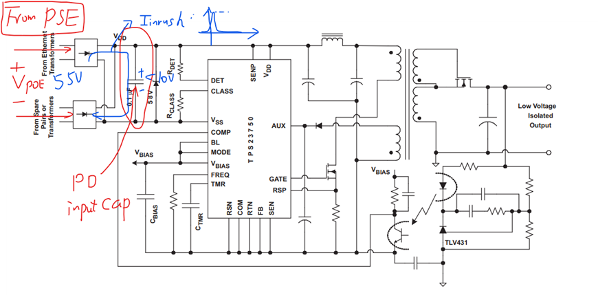
I have a question about the TPS23750.
When VDD is repeatedly turned ON→OFF→ON, an inrush current of about 4A occurs. I would like to confirm whether this can be prevented, or whether the TPS23750 is operating as specified.

(1) First, let me confirm the conditions for the inrush Limit. I understand that the 140mA inrush Limit function activates when VRTN exceeds 12V. Is this correct?

(2) VDD is repeatedly turned ON→OFF→ON. The interval between ON and OFF operations is short.
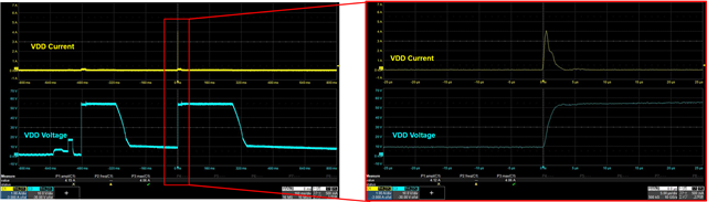
To be more specific, the power supply hub negotiates to supply 4% power, then immediately turns OFF. When it is turned ON after that, an inrush current of about 4A occurs.
It seems that turning it ON without negotiation prevents the inrush limiter from activating, causing an inrush current occurs.
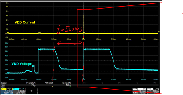
Below are the waveforms of VDD ON/OFF and the inrush current.

The inrush Limit is not operating. Please explain how this phenomenon works.


Best Regards,
Ishiwata

  • HI Ishiwata,

    Thanks for reaching out.

    (1) First, let me confirm the conditions for the inrush Limit. I understand that the 140mA inrush Limit function activates when VRTN exceeds 12V. Is this correct?

    A: The inrush limit will be activated in two cases: a) VDD exceeds the UVLO_VDD. b) VRTN-SS voltage exceeds 14.8V for longer than 1.8 ms.

    (2) VDD is repeatedly turned ON→OFF→ON. The interval between ON and OFF operations is short. It seems that turning it ON without negotiation prevents the inrush limiter from activating, causing an inrush current occurs.

    A: According to the waveforms you provided, the case is that the PSE is not turning off before the re-plug. The PSE port will be kept open for several hundred milliseconds (320 ms for 802.3bt). When the cable was plugged to PD port with PSE port open. The ~55V will charge the input cap instantly to 55V. According to the current waveform calculation, the results is at input capacitance level. This is expected to the standard PSE and PD. It's not related to the current limit function.

    As aforementioned, the maintain power time is regulated to 320ms by the standard. The unplug and re-plug time needs to be longer than this duration (> 500 ms suggested) to prevent this surge current. 

    Is this current cause any major issues on the board? Did you observe any damage to the board?

    Best,

    Zhining

  • Hi Zhining,

    Thank you for your reply.

    I understand that inrush current is an operation generated by the PSE and PD.

    There is no damage to the board, but the inrush current was larger than expected, exceeding the rating of the protection element in the previous stage.

    Best Regards,
    Ishiwata

  • Hi Ishiwata,


    May I know the capacitance of the VDD-VSS on your board?

    And may I know what type of protection element that is at risk due to this current?

    As we can see from the waveform, this current only has a duration of 1 - 2 µs. For this duration and amplitude, we didn't see a major issue in existing design and it's 802.3BT standard compliance. We would like to know the application and protection elements that requests this type of fast over-current protection and see if we can help improve in different perspectives.

    Best,

    Zhining

  • HI Zhining,

    Thank you for your great support.

    Since there is no other information available other than that the fuse rating has been exceeded, we have not received any reports of any damage to the board.
    I will pass on your advice to the customer and check the application.

    I have additional questions.
    (3) Assuming the TPS23750's inrush limit conditions are met, is it possible to suppress this inrush current?
    (4) You answered that the inrush current in this case is an expected behavior for the PSE and PD, but in what cases can the TPS23750 limit the inrush current?
    (5) In your answer to (2), does the input capacitor refer to the capacitor mounted on the PoE power supply end? Or is it the PoE Input Capacitor mentioned in the datasheet?

    Best Regards,
    Ishiwata

  • Hi Ishiwata,

    Since you mentioned about the fuse rating, typical traditional fuses are thermal related mechanism. And it typically takes couple milliseconds or longer to be triggered. The inrush current we mentioned here is at 1-2 µs level, which should not be a concern. You may check with customer to have an amp vs time curve to have a better view. 

    (3) Assuming the TPS23750's inrush limit conditions are met, is it possible to suppress this inrush current?

    A: This inrush can be considered as the PSE output capacitor charging PD input capacitor through the cable, after an extremely short gap. Since the maintain power feature regulate the delay time before PSE shutdown port, to keep compliance with the 802.3BT standard, this duration should not be less than 320 ns. In a non-compliance system, this shutdown delay time maybe adjusted.

    Generally speaking, this is a RLC charging curve for this inrush current. The PD side input capacitor is regulated in 802.3BT to be not less than 0.1 µF as well. To reduce the current amplitude,

    1. we can also make cable length longer to increase the line impedance/resistance. 

    2. Or increase the time between unplug and replug to be longer than 500 ms. In this case, PD and PSE will redo the handshake, thus the inrush current will be limited to be less than 140mA. (In your original waveform, the time between unplug and replug is ~320 ms, increase this time to be >500 ms). 


    (4) You answered that the inrush current in this case is an expected behavior for the PSE and PD, but in what cases can the TPS23750 limit the inrush current?

    A: Please refer to answers to (3), when the unplug time is longer than the maintain power delay(typically >500 ms), the PD and PSE will need to redo the handshake. The inrush current limit function will kick in.


    (5) In your answer to (2), does the input capacitor refer to the capacitor mounted on the PoE power supply end? Or is it the PoE Input Capacitor mentioned in the datasheet?

    A: The input cap in that answer is referring to the PD side input capacitor which is Cvdd, shown in the following diagram.

    Best,

    Zhining