A related question is a question created from another question. When the related question is created, it will be automatically linked to the original question.
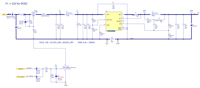
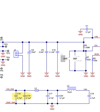
1. recommend adding filter capacitances before ferrite bead L3, as suggested in the device EVM
2. Can add decoupling capacitor of ~100pF at input [along with the caps present in current schematic]
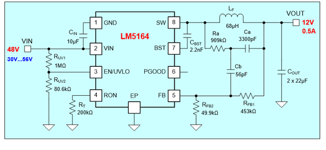
3. Ra [R2] needs to be decreased to ~550kohm to have sufficient ripple amplitude at FB note, especially at minimum output voltage.
3. Kindly note: 2*22uF, 25V rated output capacitors might not provide sufficient capacitance at 12V due to derating/dc bias effect. Effective capacitance would be ~2*8.8uF at 12V output. Customer might want to increase output capacitance based on allowable output voltage ripple.
4. What is the exact load current <1A??? Note that required inductor value has to be calculated so that the (load current+0.5*peak to peak inductor current ripple)< minimum value of peak current limit threshold of the device.
For load current ~1A, would recommend increasing inductor value ~120uH to avoid hitting current limit, especially at higher input voltage.
Ra [R2] needs to be decreased to ~550kohm to have sufficient ripple amplitude at FB note, especially at minimum output voltage.
Ans:I have a question about this part. Your calculations suggest 909kohm, so do I still need to put <550kohm?
Kindly note: 2*22uF, 25V rated output capacitors might not provide sufficient capacitance at 12V due to derating/dc bias effect. Effective capacitance would be ~2*8.8uF at 12V output. Customer might want to increase output capacitance based on allowable output voltage ripple.
1. The required ripple injection resistor is calculated as per nominal input value. To ensure that there is sufficient ripple at min Vin also [ as minimum vin is lesser than nominal], it is recommended to take this into account. You can adjust the Ra to have sufficient margin. You can use Ra ~700kohms also that should also be fine.
2. I would like to highlight that the effective capacitance of 22uf, 25V at 12V output voltage would be ~8.9uF. You may want to adjust the required capacitance based on allowable output voltage ripple.