A related question is a question created from another question. When the related question is created, it will be automatically linked to the original question.
If you have a related question, please click the "Ask a related question" button in the top right corner. The newly created question will be automatically linked to this question.
Hi, i am James, I am using the LMG5200 for an RF heater application with a frequency below 5MHz. I plan to use two LMG5200 devices to form an H-bridge, controlled by two sets of synchronized symmetrical PWM signals with dead time generation to drive the high and low sides.
PWM1 is connected to the high side of U8 and the low side of U9. Is it appropriate to use the same PWM signal to drive the MOSFET gates of both LMG5200 devices in this way?
PWM2 is connected to the low side of U8 and the high side of U9.
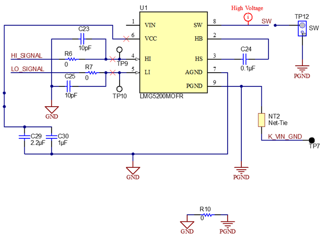
The LMG5200 EVM reference board uses a half-bridge configuration. Is it feasible to use it as a full bridge and operate properly at 5MHz frequency?
Is it appropriate to power the VCC pins of both LMG5200 devices using a TPS61322 regulator?
Is it suitable to use an INA281 for current sensing on the low side of the H-bridge in this design?
Yes, you can have a common signal for driving High side of one device and low side of another.
As long as the Voltage regulator ensures the recommended voltage level req at the VCC, there's no issue here.
The gate driver of the device is capable of driving it at 5MHz. The switching losses for the target application circuit and thermal design will be deciding factor for ensuring operation at high switching frequency.