UCC21220: UCC21220 overheating when high-side MOSFET powered from 155 V DC bus (low-side OK)

Part Number: UCC21220

Tool/software:


I am facing an issue with the UCC21220 gate driver in my design.

Setup:

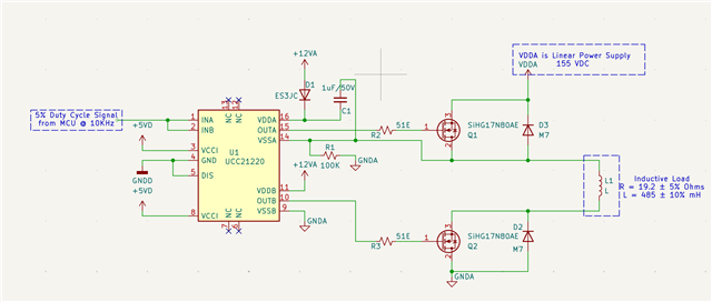
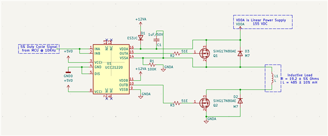
Gate driver: UCC21220, powered from a 12 V DC linear supply.

Power MOSFET: SIHG71N80AE.

DC bus: +155 V DC on MOSFET drain.

MCU provides a 5% duty cycle PWM signal.

All grounds are common (driver COM tied to bus return). 

Observations:

With only the 12 V supply connected, both low-side and high-side outputs from UCC look correct.

Low-side MOSFET drive works fine even when the HV bus is applied.

The issue appears only on the high-side:

When the +155 V DC bus is applied, the 12 V supply collapses to ~4–5 V.

The UCC21220 IC starts heating up quickly.

After a short time, the driver becomes non-functional (appears damaged). 

What I’ve verified:

12 V supply is stable until the HV bus is applied.

Decoupling capacitors are placed close to VCC.

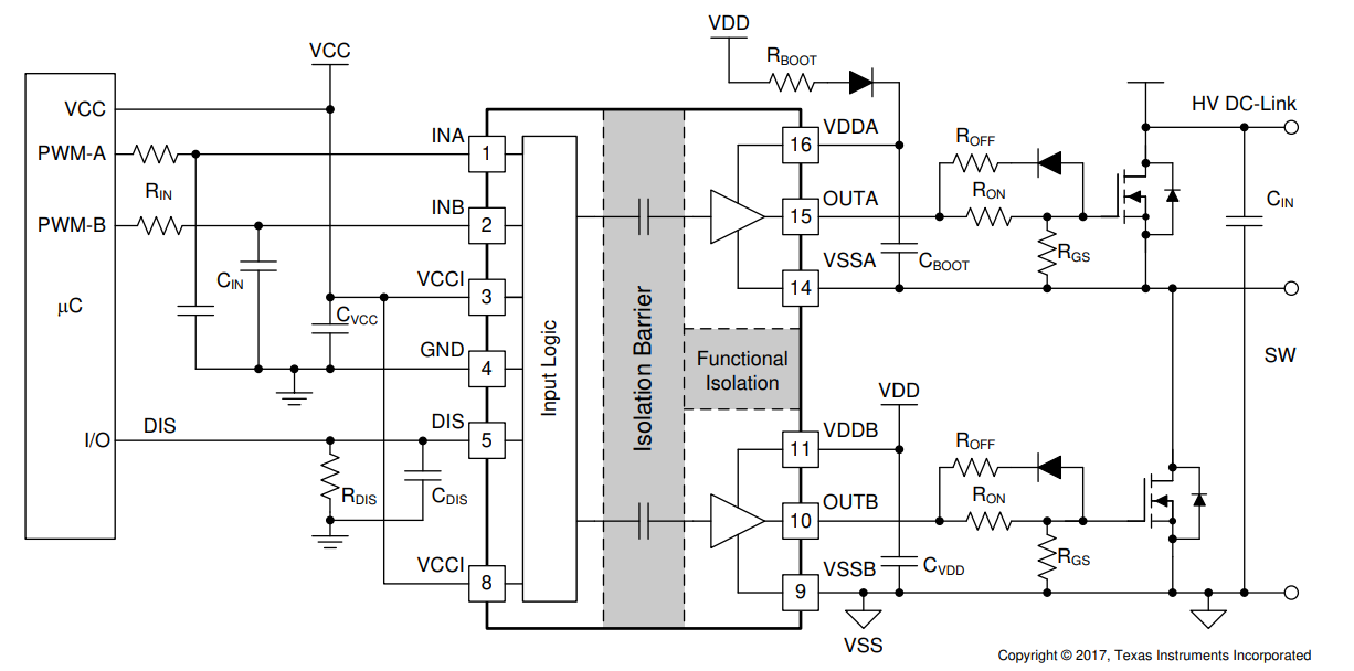
Bootstrap network is connected as recommended in the datasheet (schematic attached).

No visible shorts or solder bridges.

 
Thanks,
Smit Patel

  • Hi Smit,

    In your schematic, the DC Bus voltage appears to be connected to the VDDA pin. This is not the intended functionality of the device, and supplying the VDDA-VSSA pins with 155V is outside of the absolute maximum specs of the device. Feel free to double check your schematic with the Typical Application Schematic provided below, and let me know if you have any other questions.

    Best regards,

    Will


  • Hi Will,

    Thank for your reply!

    The schematic I originally attached was incorrect. The issue shown there is not present in the actual PCB. I have now attached the updated and correct schematic for reference.

    Thanks,
    Smit Patel

  • Hi Smit,

    Based on your comments, it seems like the gate driver is behaving as expected whenever the bus voltage is not connected. However when it is connected, only the high side output is behaving abnormally. Is it possible that the MOSFET connected to the high side output is damaged? It seems like the low side MOSFET is functional, but i wanted to confirm whether or not the high side MOSFET is also working as intended.

    Best regards,

    Will

  • Hi Will,

    MOSFETs are working as expected. I interchanged them to test it.

    Thanks,

    Smit Patel

  • Hi Smit,

    I have a few recommendations to your schematic that may help to solve this issue. Let me know if either of these help to solve the issue you described.

    I noticed that there is not a bootstrap resistor connected to the bootstrap circuitry. This is a required element of the bootstrap configuration, and excluding it may result in heightened current during power-up. I believe that including one may help to solve this issue when the DC bus voltage is powered on. Feel free to read up on this Application Note that explains the bootstrap configuration component selection in further detail: https://www.ti.com/lit/an/slua887a/slua887a.pdf

    I also noticed there is a 100kΩ resistor between VSSA and VSSB. After making the adjustment to the bootstrap circuitry, I would also recommend to open this connection, as it is able to impact the isolation ratings of the device, mainly in regards to the creepage distance between the output channels.

    Best regards,

    Will