


Tool/software:
As stated in a previous answer under the title 'TPS65150: Fault delay function question'...it is pointed out that the output rails need to be stabilised before FDLY delay ending or the chip may not function.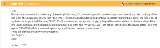
But, for any output to be stable, AVDD need to be running and to be able to function, the switching need to start.
Which switching happen only after FDLY delay is passed. Same as for the monitoring of outputs stability.
This is for the input voltage to be stable before delay pass and not the ouputs, but the same phrasing is in the datasheet and bring more confusions than anything..
Other discussions point out that there is a set delay value internally to NOT get over with our FDLY delay sets by the capacitor we put on this pin (3).
The datasheet doesn't seem to state such delay.
There is, at least, a suggested set value for the capacitor (100nF) in the datasheet. But, not really any details in regard of a too high capacitance value and the dangers (danger 'ish' since it will just prevent the chip to run)?
Does this value should be a bit above, around or lower the combine set values of DLY1 and DLY2, or it doesn't matter? Mind this, I understand that those two are to create a little delay to make so VGL and VGH get to stability...my guess is those two are starting after FDLY is over?
But does the combine values have to be lower the previous stated internal delay to avoid chip to never start?
Reason I point that out... on our side we've got a system using this chip with an input of 3.3V to get AVDD to 11V, VGL to -10 and VGH to 20V for our screen to function.
We've put down FDLY to 100nF, DLY1 and DLY2 to 22nF each and sometimes (five different boards until now out of 20ish) it doesn't start properly or just at all.
I've point out the possibility of never start if with a too high cap value on FDLY...hence my questions above and the necessity of clarifications.
Thank you
Jonathan
