


Tool/software:
Hello,
We have designed a similar HB LLC converter based on the UCC25640EVM-020. During our testing, we observed an issue where the secondary current is going into the negative direction instead of stopping at 0A when the synchronous rectification MOSFETs Q4 (Q16) and Q2(Q15) are populated along with the IC UCC2424DR.
Interestingly, when we disable the gates of Q4 and Q2, allowing the MOSFETs to operate in body diode mode, the secondary current does stop at 0A. We have also noted similar behavior on the LLC EVM UCC25640EVM-020 board.
Could you please provide an explanation for why the secondary current is going into the negative direction instead of stopping at 0A? Additionally, we would like to understand if this behavior could potentially increase losses in our design.
Please find waveforms for your reference:
Our Design Sec side waveforms (Vin=360V, Vout=12V, Turns ratio=15.83, Lm=500uH, Lr=100uH, Cr=12nF, max output power=60W):
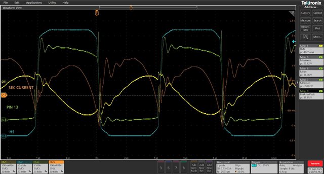
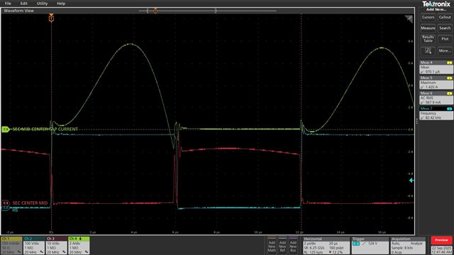
1. Our Design Sec side waveforms 28W output: (Q2 in EVM is equivalent to Q15, and Q4 in EVM is equivalent to Q16)
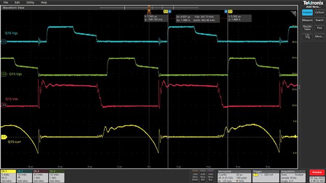
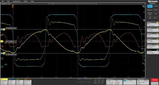
2. Our Design Sec side waveforms 28W output:
Blue=HS node voltage, Green=Transformer Sec winding voltage, Yellow=Primary current, Orange= Sec Current
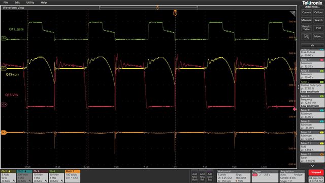
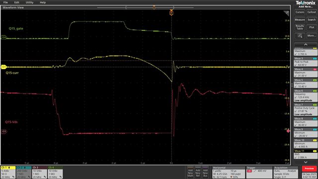
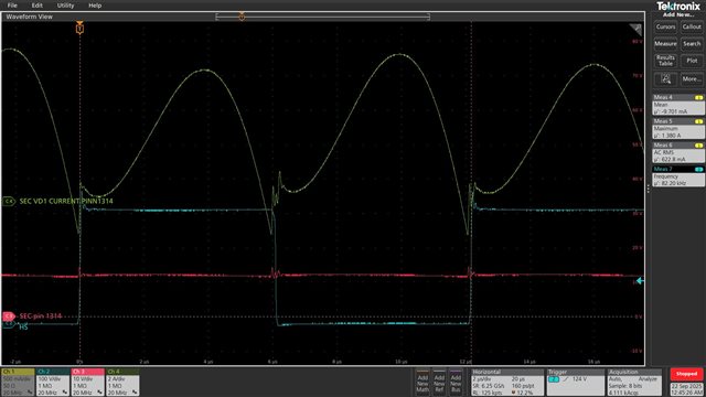
Diode Mode: MOSFET Gate disable:
Blue=HS node voltage, Green=Transformer Sec winding voltage, Yellow=Primary current, Orange= Sec Current
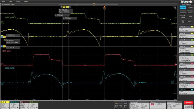
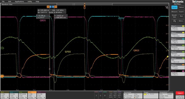
Primary Side Waveforms: Q7-HS MOSFET, Q8-LS MOSFET
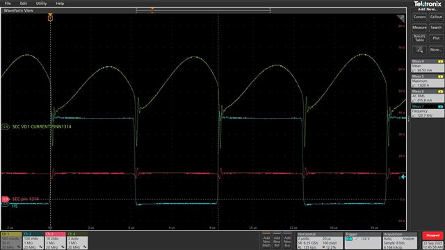
UCC25640EVM-020 Waveforms:
Vin=335V, Vout=12V
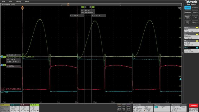
Vin=400V
Please let me know if more information is needed.