Other Parts Discussed in Thread: LM74502, TPS26750, PMP41115
Tool/software:
Good day, collegues,
My customer would like to integrate USB-C PD 3.1 EPR charging into design.
Objectives are:
- To enable charging of my battery via USB-C across the full power range defined by the USB-C PD 3.0 and 3.1 standards.
- To also allow charging of a smartphone from my battery.
For voltage conversion, I am using an I²C-controllable Buck/Boost converter. I plan to implement the TPS25750 together with the TPD4S480RUKR, and I have a few questions:
- Why does the TPS25750 provide an internal power path for SPR mode, while in EPR mode the circuit switches to an external MOSFET?
- Is it possible to use the TPS25750 purely as a controller, routing power through an external MOSFET in both SPR and EPR modes?
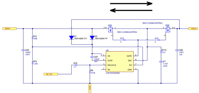
- In my design, the power path will use two NMOS devices driven by the LM74502. If I do not use the internal power path of the TPS25750, can the POWER PATH EN pin be used to drive the Enable input of the LM74502, or does this signal necessarily need to be handled by my microcontroller?
- If I use only an external power path, am I correct that I don’t need to connect the following pins?
- TPD4S480RUKR: VBUS_LV, EPR_BLK_G, VBUS, VBIAS, EPR_EN
- TPS25750: VBUS
Thank you,
Daria