


Tool/software:
Dear TI Support Team,
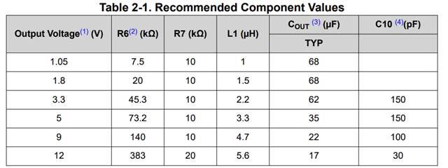
I’m designing with a TI buck regulator whose datasheet/EVM table lists example feedback resistor pairs (R6 top / R7 bottom) for various output voltages. I understand those values are recommendations rather than fixed requirements, as VOUT is set by the divider ratio.
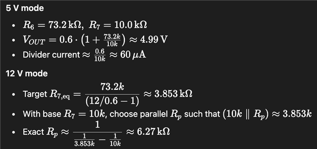
For my application, I would like to select between 5 V and 12 V by switching the bottom feedback path (R7) with a MOSFET in parallel:

Before I finalize this approach, I’d appreciate your guidance on the following points:
-
[General Validity]
Is it acceptable to deviate from the resistor values shown in the table as long as the divider current remains in a reasonable range (e.g., a few tens of µA to ~100 µA) and VOUT is correct? - [Inductor selection]
For the inductor, the guide recommends 3.3 µH for a 5 V output and 5.6 µH for a 12 V output. In this case, is it acceptable to use 5.6 µH for both outputs?
(or.. is 3.3uH Okay? - I want to use 3.3uH for cost efficiency) -
[Transition Behavior]
When switching from 5 V to 12 V (or vice versa), do you recommend disabling the converter via EN first to avoid output glitches, or is it acceptable to switch R7 in-circuit if we limit the gate slew (small RC on the MOSFET gate)? -
[Compensation / Cff Interaction] - Cff is specified in the datasheet schematic.
If a feed-forward capacitor (Cff) from VOUT to FB is used per the datasheet, should we retune Cff for the two output settings, or is a single value typically adequate for both 5 V and 12 V with this device?
I plan to prototype both modes and validate stability (phase margin) and transient response at VIN min/max and full load. Any additional best practices or application notes you can share would be greatly appreciated.
Thank you for your support.