LMR51610: LED Brief Drop During Stop Input

Part Number: LMR51610

Tool/software:

Hi [TI Support],

I am observing unexpected behavior with the LMR51610XDBVR LED driver in my current setup and would appreciate your guidance:

  1. Tail input only: LED turns on instantly (as per the schematic).

  2. Tail + Stop input: LED reaches full brightness instantly.

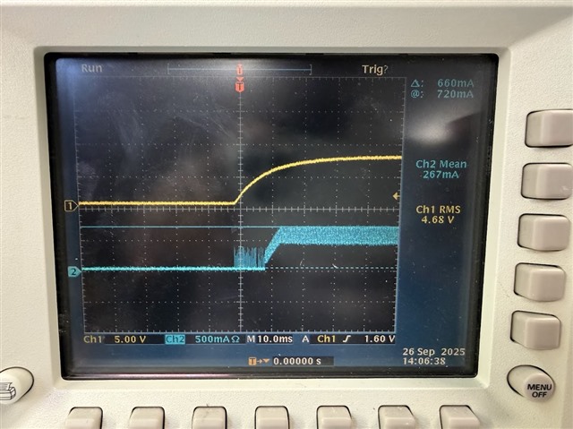
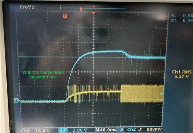
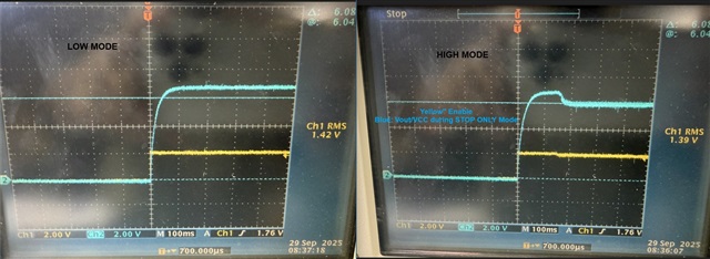
  3. Stop input only (without Tail): LED initially turns on, then briefly turns off for a few milliseconds before returning to full brightness.

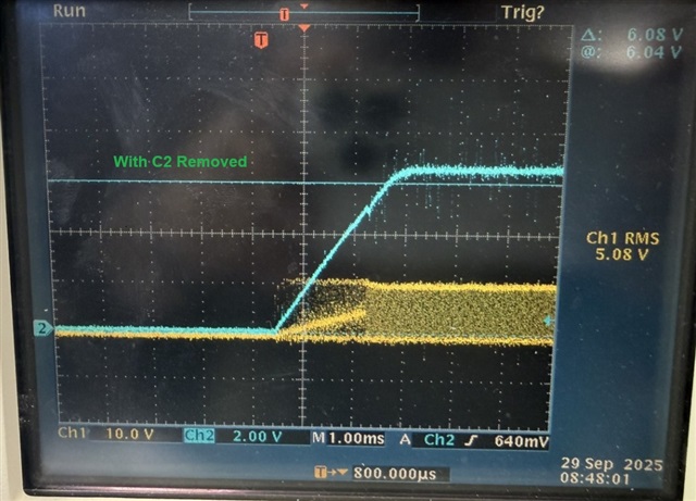
On my bench, increasing the buck converter output voltage by ~1 V appears to resolve the issue. The actual Vout is approximately 10% lower than the calculated value, giving 6.10 V, whereas the LED regulator requires ≥6.7 V for proper headroom. I am not certain if this is the root cause or the definitive fix.

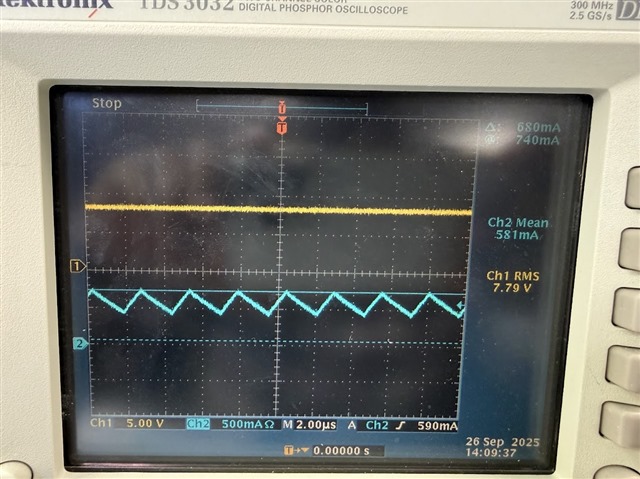
There is no issue during steady-state operation; the LED operates normally once at full brightness.

Additional points:

  • Estimated LED load current: 400 mA

  • Each LED forward voltage (Vf): 3.1 V max

  • Stop input is toggled ON/OFF every 1 second in flasher mode. I would like to confirm if the driver’s transient response can handle this without undesired behavior.

  • Previously, with AP64060Q, this behavior was not observed; the issue appeared only after switching to the TI driver.

Could you advise if this behavior is expected, or if there is a recommended configuration for Tail/Stop inputs to avoid the brief LED drop?

Thanks in advance for your support.

A

V

  • Hello Reddy,

    Thanks for the query!

    Can you kindly clarify clearly what are the input and output conditions for the device along with the frequency of operation during this phenomenon?

    Also, the feedforward circuit (C3) seems too high, kindly reduce it to order of 100pF and observe if it helps.

    As said by you, the problem occurs only when only stop input is triggered, that to during startup. (Kindly correct me if wrong.)

    Only difference between stop path and tail path is the extra path leading to resistor divider leading to the Full pin.

    At which input voltage do you see this behavior, is it for the full range of 10-30VDC?

    Can you kindly probe the Enable pin and see its waveform during the aforementioned phenomenon during the startup?

    Also, can you probe the pin 1 of the L2 inductor and see if there is any difference between the 3 cases you mentioned (Tail, Tail+Stop, Stop)?

    Also, is the point where the feedback ladder for the LMR51610 to the Vout has 10% less voltage than what is expected?

    Thanks and Regards,

    Sourish Nandy.

  • The input voltage range is 10–30 VDC.
    Replacing C3 with 100 pF did not show any improvement.
    The issue occurs only in STOP mode during startup.
    The Enable signal has been verified and is clean during startup (waveforms attached).
    The problem is observed across the entire input range.
    We identified the root cause: C2 = 0.1 µF across R1. Removing C2 resolves the issue.
    Attached are the waveforms with C2 in place and with C2 removed.

  • Hello Reddy,

    Thanks for the clarification.

    As stated by you too, I mistook took the symbol from the schematic.

    As written in my reply, I meant to change the C2(Feedforward cap across Rfbt) to around 100pF and not C3. 

    From the QuickStart calculator the system's Phase margin is below 45 degree with the C2 value of 0.1uF you used.

    Kindly change it to 100pF for system stability, as from QuickStart Calculator it indicates some stability issue can occur.

    I am attaching the QuickStart calculator below.

    LMR516XX--DESIGN-CALC_REVA1.xlsm

    Kindly share if it improves.

    Thanks and Regards,

    Sourish Nandy