TPS63900: Supercap charging, reverse current blocking in shutdown

Part Number: TPS63900


Tool/software:

Hi,

Following the discussion in this thread: TPS63900: Supercap charging

We use a Supercapacitor as our main energy storage element. It is mainly charged by solar power, but should also be charged with a primary battery as a backup.

For this we use the following circuit (the supercap is not shown, but is connected to VCAP), which charges the Supercapacitor up to 3V, whenever it should fall below that threshold. The supercap voltage can also be higher, if it is charged by solar.

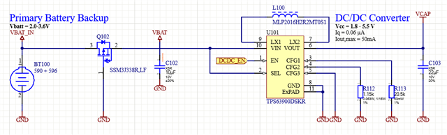
Can you please confirm that the schematic shown is correct?


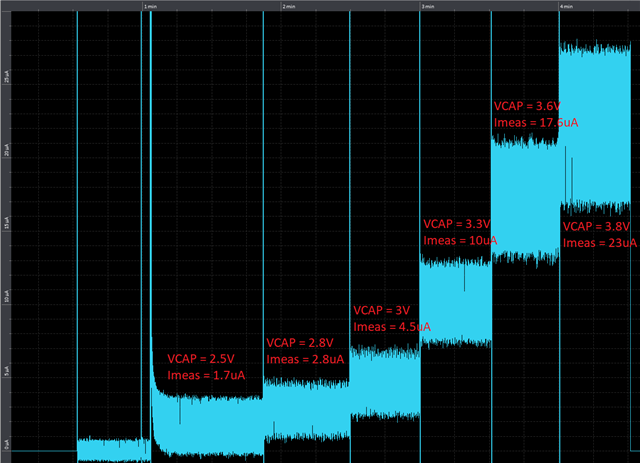
However, the circuit should also be usable if no backup battery is inserted (VBAT_IN is floating). But right now I measure a large reverse current going into the VOUT pin of the TPS63900, depending on the supercap voltage up to 23uA at VCAP = 3.8V.


Is this behaviour normal? Can the reverse current flowing into the TPS63900 be avoided?

  • Hello Steven,

    Do you have the primary battery connected for this test? Is the device enabled or disabled?

    Best regards,
    Brigitte

  • Hi Brigitte,

    The primary battery is not connected for this test. As I stated above, we want the device to also work without the primary battery.
    The EN pin of the TPS63900 is pulled high for this test.

  • Hello Steven,

    The device needs some energy to operate. If it cannot draw it from the input, it will draw it from the output. I expect that the device keeps the input voltage at a certain level and therefore switches.

    What is the reason for keeping the device alive when there is no primary battery?

    Best regards,
    Brigitte

  • As mentioned in my post, the primary battery is not necessary to run the device. The supercapacitor is usually charged by solar. The primary battery is optional and can be used if our customer fears that the solar energy will not be sufficent all the time.

    I understand that the TPS63900 chip needs some energy to operate. However, since the quiescent current and shutdown current are in the nA range (75nA / 60nA) I am surprised to see such a large leakage current into VOUT. If I understand you correctly this reverse current is expected and can not be avoided, right?

  • Hello Steven,

    The expert for this device is in public holiday at the moment. I am not sure if the values are as expected, but some current from VOUT will be drawn as the device needs to stay alive. Please expect a final answer end of next week.

    Best regards,
    Brigitte

  • Hi Steven,

    I verified on EVM and similar leakage into Vout pin was observed. I also checked that if pull the EN to low, when Vout >= 2.8V, the leakage into Vout pin can be reduced to ~10nA. But if the biased Vout is 2.5V, there is still a ~1.7μA leakage into Vout pin.

    In you application, can the DCDC_EN be pulled low when the battery is not inserted? That is, when there is no battery, disable the device can reduce the leakage into Vout pin significantly. 

    Regards

    Lei

  • Hi Lei,

    Thanks for your answer, these results match with my measurements. Unfortunately, that means that overtime, the LiC Supercap that we use will be drained and thus damaged. We are currently reworking our power concept for this design, because the TPS63900 does not seem appropriate for our needs.

    Kind regards,

    Steven