TPS7H4013-SEP: Slope Compensation and Inductor Sizing

Part Number: TPS7H4013-SEP
Other Parts Discussed in Thread: TPS7H4013-SP

Tool/software:

Hello, I have two questions for TPS7H4013-SP:
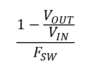
1) Slope compensation have two formulas Vout[V]/Inductor [µH] or Inudctor ripple value [mA]/ offtime conduction [ns] 
when I use my data Vout=6,9 Inductor = 26µH gives SC=0,27 A/µs or Inductor ripple value 0.48 A and offtime condcution 306ns gives RSC 1,59 
which will result in whether 50k or 750k for SC resistor. 
which one is the right value ? 

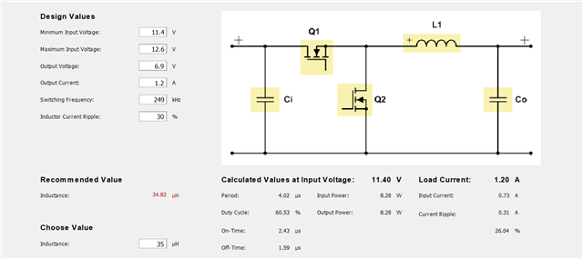
2) the power stage design gives different value for Inductor and Ripple relative to the equation in the datasheet, which one to follow ? 
the datasheet equations gives 25µH while power stage designer gives 35µH 


BR,
Mohamed

  • Hi Mohamed,

    Both methods will give you the inductor down-slope for slope compensation. I believe the off-time you were using (306ns) is just incorrect. Off time in µs can be calculated as:


    For VIN = 12, VOUT = 6.9, and Fsw = 249kHz, off-time = 1.707µs = 1707ns

    So with 480mA of current ripple and 1707ns of off-time I can calculate 0.281 A/µs inductor current down-slope. Of course this also works with using A and µs instead of mA and ns.


    Regarding your second question, which equation in the datasheet are you trying to follow?

    Using equation (10) along with the inputs from your power stage designer screenshot I calculated 34.82µH, which is the same inductance that power stage designer recommends.

    As for the ripple, I was able to match what power stage designer is calculating using equation (11) in the datasheet and using the "minimum input voltage" instead of the "maximum input voltage", which is also what power stage designer uses for its calculations in the bottom right.

    Thanks,

    Andy