Tool/software:
Hello.
This is the second post regarding this. Below is the link for the first post.
e2e.ti.com/.../tps62826-as-an-inverter-converter-is-it-possible
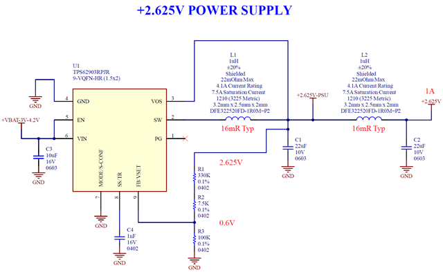
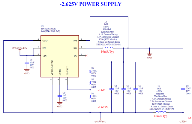
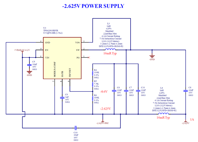
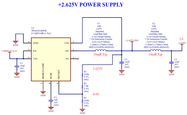
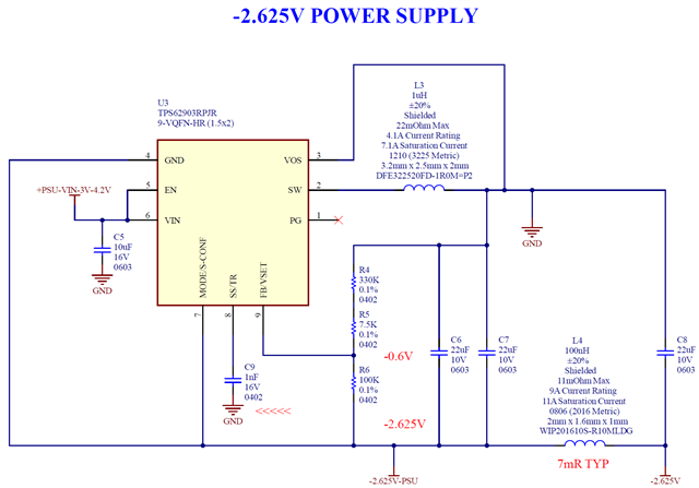
Below are 2 pictures, of my schematics for positive and negative supplies, +- 2.625V x 1A each. 1A is enough for my project.
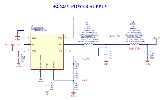
(1) "+PSU-VIN-3V-4.2V" would be a 1-cell Li-Ion battery.
(2) On the second picture, which is the negative PSU, the bottom side of C9 is connected to GND. Is this ok? Or in this case it should be connected to the -2.625V negative rail? I did not see the connection of SS/TR pin on the application note of the first post.
(3) On the second picture, which is the negative PSU, I placed at the output 2x 22uF/10V/0603 ceramic capacitors. I did not placed 3 capacitors (as shown on the application note) because I only need at maximum 1A of current, and in this case, I ask if I could use just one 22uF at the output, for reduction of PCB space, because PCB space is very limited in my project.
(4) Inductors L2 and L4 have 100nH, and inductors L1 and L3 have 1uH. Would the engineer of Texas Instruments recommend to use L2 and L4 as 1uH also? Use for L2 and L4 the same part number of L1 and L3? The advantage of L2 and L4 being 100nH, is that the 100nH part number is smaller, and space is at a premium in my PCB layout.
(5) The 22uF/10V/0603 capacitors would have defined part number, they would be GRM188R61A226ME15D (of Murata) or CL10A226MP8NUNE (of Saamsung). I'm placing below a picture of their DC bias and impedance/ESR curves, just as reference.

(6) Here is the Webench design that I got:
TPS62903 Webench Design - VIN 3V to 4.3V - VOUT 2.625V x 1A.pdf
(7) Observations?
Yes, I'm posting this on the weekend, and I'm from Brazil.
Regards,
Jeferson Pehls.