Tool/software:
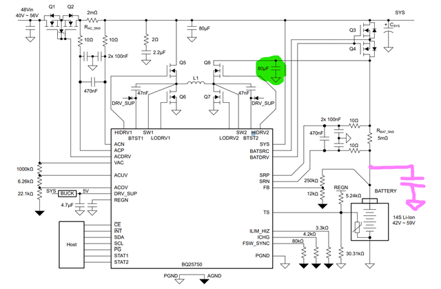
Hi. I am helping to debug battery charger design with BQ25750.
PSU voltage is 48V. Battery being charged is LiFePO4 15 series, with 3A.
I have added a ZIP file with 3 images of a part of schematics and PCB layers too.
2 boards have failed after some time while connecting battery and updating firmware of MCU located on the board.
- An interesting symptom is that when the IC fails, it draws current through 10 ohm series resistors connected form battery current sense resistor to SRN and SNP pins. Resistors heat up to approx 40 degrees.Forgot to measure the current. Do you have any idea what kind of event would cause this? SRN and SNP difference can be max 0.3V which seems unlikely achievable on 5mOhm resistor, it would need 60 Amps, and inrush current of this board should not be that high.
- Can you please check PCB design a bit. In my opinion 2 Layers for this board is not enough and bottom layer is badly designed with very big loops for return currents which would definitely cause EMC problems, and possibly issues with board even working correctly. Do you agree?
- Another thing which seems bad- ICs i2c is connected without TVS or any other protection to 10cm long trace which is then connected to 50cm long cable going to battery BMS. It seems that
I am still trying to find out what causes IC to die. I would appreciate any input.