UCC28180: Input Current Shape

Part Number: UCC28180


Tool/software:

Team,

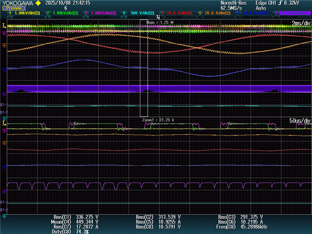
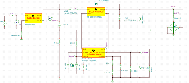
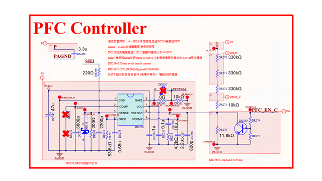
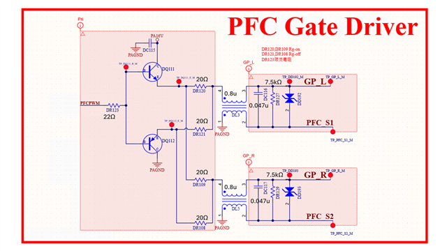
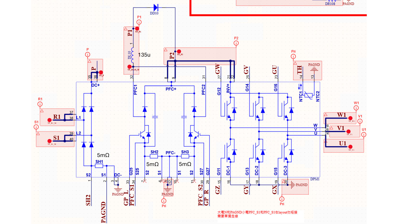
There're few questions here about the tested waveforms. The boost output DC bus works up to 435V, it's ok. But its input current as waveform with CH7(Blue color) is not likely as pure SINE wave. And the the PFC's gate driver is not switching to 0V when crossing to Zero switching period. It looks that there are difference between real on-board test and SIM result.  Could you offer the comment to improve it! Thanks. 

Application: AC inverter Motor Drive

CH1 : U/GND

CH2 : V/GND

CH3 : W/GND

CH4 : P/N

CH5 : U Phase Iout

CH6 : V Phase Iout

CH7 : R Phase Iin

CH8 : PFC gate driver

Spec:
Vin=220V 60Hz,Iin=17A,Vo=300V,Io=10A

On-Board Test:

SIM result:

Regards

Brian

  • Hi Brian,
    Can you please share the schematic and the design calculator for this.

    Also, can you please confirm if your Vout specification is 300V or 435V?

    Thanks
    Sanchayan

  • Hello,Sanchayan

    Please see the attached files for the partial schematic and the design calculator.

    Regarding the voltages, the DC bus voltage is 435V and the motor output voltage is 300V.

    Thanks!

    5HP.xls

  • Hi Chienhao,
    In the design calculator that you shared the LI_ripple_factor(target)  value is high. The more ripple you allow the more portion of the inductor current will start operating in discontinuous mode and your line current THD will start to increase. This is the reason the current shape is deforming. If you reduce this inductor current ripple factor value the required inductor value will increase, and more portion of the line current will operate in continuous conduction mode. As a result, the line current THD will reduce which will improve the current shape.
    Thanks
    Sanchayan

  • Hello Sanchayan,
    Following up on your point, I'd like to ask what a reasonable value for the Inductor Current Ripple Factor (LIripple_factor) would be? And, given that the inductor value based on the design calculator is 135μH, what value should I change it to in order to effectively reduce THD and solve the zero-crossing current distortion issue?

    Also, if I choose not to change the inductor, can I solve the problem by changing the CICOMP capacitor from its value of 5600pF to a lower value, or by adding a parallel RC network (DR250, DC250) to the current loop?

    Thank you.

  • Hi Chienhao,

    The peak to peak current ripple can be obtained from the equation ILpk-pk=((Vin*D)/(L*Fsw)), Where Vin and D are instantaneous input voltage and duty. When the average current goes below (ILpk-pk)/2 the converter will operate in DCM.

    If for Maximum input rms voltage Vinrmsp CCM is required for minimum power of Poccmmin with efficiency of n you can try to use the following equation L=((Vinrmsp)^2)/(2*Poccmmin*n*Fsw) for determining the inductor value.

    As you can see in the equation for the inductor, increasing the switching frequency will reduce the required inductor value. 

    Thanks
    Sanchayan

  • Hello Sanchayan,

    Based on the calculations, assuming a minimum operating condition of 10% of the rated load requires CCM operation, can we effectively resolve the zero-crossing distortion issue by increasing the inductance to 419μH?

    Additionally, I tested changing the CICOMP capacitor value to 2700pF. This appeared to improve the distortion, but the resulting current waveform (CH2) is now triangular, which seems incorrect.

    CH1: Input Voltage

    CH2: Input Current

    CH3: PFC Vge

    CH4: W Phase Vout

    Thank  you.

  • Hi Chienhao,
    In the wave form that you have shared the inductor seems to work in DCM mode in the edges of the line voltage. The inductor has to work in CCM for the ic to work properly and get lower line current THD. Try to increase your switching frequency so that the inductor current ripple will reduce and more portion of the line current will work in CCM.
    Thanks
    Sanchayan 

  • Hi Sanchayan,

    Thank you for your feedback. I agree that the DCM operation near zero-crossing is degrading the THD, and achieving CCM.However, I cannot increase the switching frequency due to the high switching losses of the IGBT module, which risks damage.

    Therefore, I will focus on the most direct solution:Increase the Inductance value,This will reduce the current ripple , extending the CCM operation range.

    My question is: By simply increasing the inductance value, can I guarantee that input current will definitely become a sine wave?

    Thanks

  • Hi  Sanchayan & Support Team,

    Is there any update?

    Thanks

  • Hi Chienhao,
    As you start to increase your inductance the portion of the line current in DCM should start to reduce and you should see improvement in line current THD. The inductor might still operate in DCM near the zero crossing but its effect on the line current THD should reduce.
    Thanks
    Sanchayan