TPS65219EVM: MSP430 Programming

Part Number: TPS65219EVM
Other Parts Discussed in Thread: SK-AM62B-P1, , TPS65219, USB2ANY, TPS65214, TPS6521905

Hi Team,

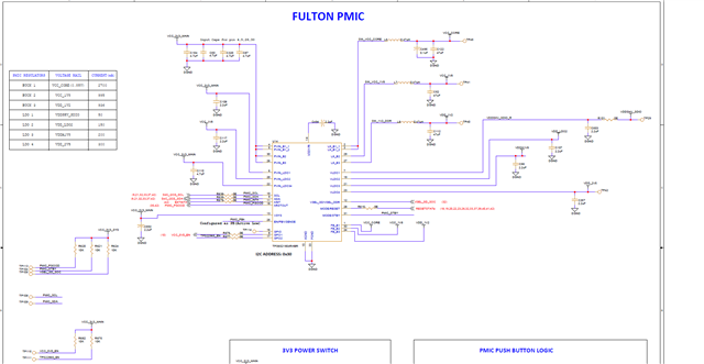
I’m working with a TPS65219EVM-SKT and a custom designed SK-AM62B-P1 reference-based board that originally had the same PMIC (TPS65219) mounted. My onboard PMIC failed, so I attempted to power my custom board by connecting the outputs from the TPS65219EVM (BUCK1/2/3, LDO1–4, etc.) directly to the board. Unfortunately, while testing, my EVM’s PMIC and MSP430 got shorted, and now I plan to replace both components on the EVM.

I have a few questions before proceeding:

  1. MSP430 Programming:

    • After replacing the MSP430 on the EVM, how can I reprogram it?

    • Is there a binary (.hex/.txt) file available for the factory default firmware used on the TPS65219EVM?

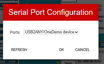
    • Which tool and interface should I use (USB2ANY, MSP430 BSL, or any other TI utility)?

    • Could you please share the correct connections and steps to flash the MSP430?

  2. EVM-to-Custom Board Connection:

    • What are the essential pins/signals that must be connected between the TPS65219EVM and my custom board to correctly power and control it?

    • Do I need to connect the I²C (SCL/SDA), GPIOs, or enable signals (nPWRON, PGOOD, EN pins) between the boards, or are only the BUCK/LDO outputs sufficient?

    • Any recommendations on grounding or pull-up resistors when using the EVM as an external power source?

My goal is to use the TPS65219EVM to power and control the custom board safely, while restoring full functionality of the EVM after replacing the damaged parts.

Thank you for your support!

Regards.

  • Hi Mallika, 

    1. MSP430 can just be updated with the USB2ANY explorer tool, and this will automatically install the latest firmware update (2.8.2.0), this is compatible for the TPS65219EVM. 

    With the USB cable plugged in, opening the explorer should prompt a pop-up window asking to update to 2.8.2.0 if it detects this is not the current firmware version installed. 
    If the pop-up does not come up automatically, got to Advanced > Update Firmware and follow the instructions pop-up instructions. 

    2. Can you clarify, are you using the TPS65219EVM-SKT or just the TPS65219EVM?
    The socketed TPS65219EVM-SKT is not designed to be attached to heavy loads, this should only be evaluated with the TPS65219EVM (solder-down, non-socketed).

    Are any of the GPIO signals being used to drive any other components in your system? If these are unused, then there's no need to connect them. 

    I2C lines should be connected in order to read/write to the PMIC.

    If EN is supplied by a signal from the processor, then this needs to be connected between boards.
    If EN is just tied high to VSYS as it is on the EVM, then as long as VSYS is being supplied to the PMIC EVM, this is fine. 

    nPWRON and PGOOD are not essential to powering on, only connect these if you want to evaluate how these lines communicate between the PMIC and processor. 

    Let me know if there's any more clarity needed, as I'm not entirely sure if I understood correctly.
    Perhaps if you have a block diagram of your system, that would help me get a better idea of your ask here. 

    Best Regards, 
    Sarah

  • Hi Sarah,

    Thank you for the clarification and detailed guidance.

    I’m currently using the TPS65219EVM (non-socketed version) — not the SKT type. The MSP430 and PMIC ICs on my EVM were damaged, and I’m waiting to receive the replacement parts. Once I solder them, I plan to reconnect the USB cable and check whether the USB2ANY Explorer tool can detect the EVM.

    After detection, I’ll follow your suggestion to use the Advanced → Update Firmware option to flash the MSP430 with the latest firmware (v2.8.2.0).

    I’ll also ensure the I²C lines (SCL/SDA) are connected to my custom board for proper PMIC communication. The EN pin on the EVM is tied high to VSYS, so I’ll maintain that configuration. nPWRON and PGOOD will be left unconnected for now since I only need the EVM to act as a stable power source.

    Please confirm if this workflow is correct:

    1. Replace and solder the MSP430 and PMIC on the TPS65219EVM.

    2. Connect USB to PC and use USB2ANY Explorer to verify MSP430 detection.

    3. If prompted (or via Advanced → Update Firmware), update to firmware v2.8.2.0.

    4. Supply VSYS (5 V) input,and use BUCK/LDO outputs to power the custom board.

    Once I complete these steps, I’ll share the results.

    Thanks again for your support!

    Best regards,
    Mallika

  • Hi Mallika, 

    Yes, these steps are correct.

    Let me know if you have any updates or any questions pop up as you go through the actual process.

    Glad to be of help!

    Best Regards, 
    Sarah

  • Hi Sarah,

    Thank you for the clarification earlier.
    I’ve replaced both the MSP430 and the TPS65219 PMIC ICs on my TPS65219EVM (non-socketed) board.

    After replacement, I connected the board to my PC via USB and opened USB2ANY Explorer (v2.8.2.0), but the tool shows:

    No USB2ANY controller was found Open failed - Error: -24 Invalid handle


    and the board is not detected.

    Could you please confirm the next steps for recovering or programming the new MSP430?
    Do I need to manually load the USB2ANY firmware using the USB2ANY Firmware Loader utility, or should it be automatically recognized by the Explorer tool once connected?
    If manual flashing is required, could you please share the correct procedure or jumper settings (BSL or JTAG) to program the MSP430 on the EVM?

    Thank you.


    Regards.

  • Hi Mallika, 

    For the USB2ANY explorer flashing step:

    1. Remove external VSYS and GND connectors
    2. Change J11 jumper "EXT_LDO_VIN" to USB_5V
    3. Connect USB cable to board and PC (LEDs should turn on)
    4. Open USB2ANY Explorer- Explorer should  recognize USB2ANY controller.

    Check if the explorer is able to recognize the device after these steps, 

    Once the firmware is flashed correctly, you can change the J11 configuration back to the external VSYS and power on with the external VSYS and GND terminals.

    Let me know if the device is still not being recognized. 

    Best Regards,
    Sarah

  • Hi Sarah,


    I have done above steps and I have got this update on USB2ANY explorer:

    I have chnaged back the J11 back to external VSYS.
    I opened the TPS65219_GUI and opened the devices connected, but its not detected.
    Will the device gets detected automatically or we need to give the TI device ID and I2C_Address?

  • Hi Mallika, 

    Glad the update was able to work. 

    The GUI should automatically recognize the device when plugged in, 

    Can you go to Options > Serial Port and check if there are any inputs being detected?
    There should be a 'USB2ANY/ OneDemo device' option being recognized at the port. 

    Also make sure the USB2ANY explorer is closed/ there are not multiple tabs of the GUI open at once. 

    Best Regards, 
    Sarah

  • I can see the USB2ANY has been detected but failing to connect.
     .
    The Port has been detected as specified.

  • Hi Mallika, 

    This error may indicate an improper hardware connection, 

    Are you able to probe the VDD1P8 test pin to check if this is measuring 1.8V, indicating if the PMIC is functioning correctly?

    Or  in general, are any of the outputs outputting the correct voltage when VSYS is powered?

    Best Regards, 
    Sarah

  • Hi Sarah,

    The board has been damaged even after placing the PMIC and MSP.
    We replaced the old board and got new TPS65219EVM and reprogrammed that.
    We have not included the PMIC node in device tree. Let me know if we have to include this prior.
    Our goal is to power the SoC from PMIC.

    Please let me know if this setup is sufficient, or if any additional connections are recommended for initial validation.

    • I²C lines are connected between the PMIC EVM and the SoC for communication.

    • The EN signal is tied high to VSYS (same as on the EVM), and VSYS is properly supplied to the PMIC.

    • nPWRON and PGOOD lines are currently not connected, since we are primarily focused on verifying power-up.


    Can these connections drive the SoC.

    Regards,
    Malli 

  • Hi Mallika, 

    For the software question about the device tree, I'll let our software expert   answer this.

    Those connections appear to be correct, I just have a few clarifying questions:

    Did you replace the TPS6521401 PMIC that comes on the EVM with the TPS6521904 PMIC, as shown in the schematic?

    • TPS6521904 configured for push-button by default, so push button on the EVM will need to be pressed to enable device to active state. 
      The EVM is already configured to support PB, so no modifications need to be made, just be aware that the button needs to be pressed. 
    • Are you reprogramming/reconfiguring the device via I2C in any manner?
    • Are you connecting to I2C from the processor, or from the EVM?

    Best Regards, 
    Sarah

  • Hi Sarah,

    We designed a custom board using design files of SK-AM62B-P1 EVM. On custom board the PMIC has been damaged. we are now trying to use TPS6521EVM to configure the design board.as shown 

    On first Attempt: Reprogrammed TPS65219EVM using NVM having TPS6521901 PMIC with NVM:

    after reading register values, i just changed below register value
    BUCK2_VOUT,9,0xA4
    somehow the board has been shorted.

    In Second attempt: replaced the PMIC with TPS6521904 and MSP430 and programmed or updated firmware as seen in previous discussion, but the USB has got damaged.


    For requested questionary:

    • Did you replace the TPS6521901 PMIC that comes on the EVM with the TPS6521904 PMIC, as shown in the schematic?
      No, I did not replace the PMIC, I have reprogrammed it through the TPS65219 GUI to match the configuration and voltage sequencing of the TPS6521904 (AM62x reference profile).

    • TPS6521904 configured for push-button by default, so push button on the EVM will need to be pressed to enable device to active state. The 
      Understood. I am aware that the push-button (PB) must be pressed to enable the device to enter the active state. I have not modified the EVM hardware in this area.

    • Are you reprogramming/reconfiguring the device via I²C in any manner?
      Yes. I am reprogramming the PMIC registers via I²C using the TPS65219 GUI connected through the USB interface. The updated configuration aligns with the TPS6521904 power-up profile.

    • Are you connecting to I²C from the processor, or from the EVM?
      → The processor I²C lines are not yet connected.


    Now we bought new boards of TPS65219EVM which has same TPS6521901 PMIC.
    Can you suggest if I could reprogram the same way with desired outputs of TPS6521904 on TPS6521901 and connect them to the custom board.

    Looking forward for your comment.

    Can you include someone from software team to comment on PMIC node on custom device tree.


    Regards,
    MAllika

  • Hi Mallika, 

    Thank you for the information. 

    Generally I would recommend a TPS65219EVM-SKT board be used with TPS6521905 to program the blank NVM device from scratch, just for convenience sake. 

    But since the socketed board is currently out of stock, programming on-board with the TPS65219 EVM on the TPS6521901 is also acceptable. 

    Be sure that you are following the NVM reconfiguration steps, and programming while the device is in the INITIALIZE state only. 

    There is no concern for you to reprogram the TPS6521401 with the -04 settings and then wire to your custom board. 

    I'll ask our software team to follow up with an answer. 

    Thanks, 

    Sarah