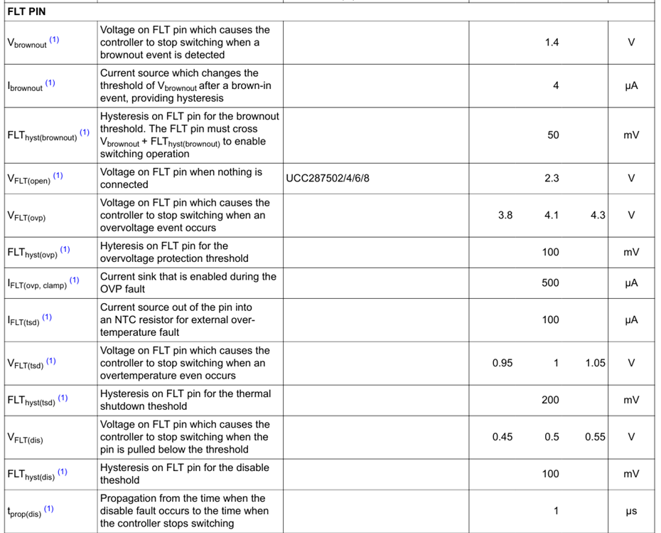
Hi,
This thread has been locked.
If you have a related question, please click the "Ask a related question" button in the top right corner. The newly created question will be automatically linked to this question.
Hi,
Hi Stas Tishman,
To debug the issue, would you please measure the voltage on FLT pin when you apply 400V and 420VDC? I believe that provides an answer.
Also, apply an external voltage through a resistor to find out which of the FLT pin thresholds are working and their behavior could tell us, if the part you were using is of a different variant instead of x2.
Please see different thresholds (and functionalities) available on FLT pin based on device variant.

Regards
Hemanth
Hi Hemanth,
Thank you for your reply.
Hi Stas Tishman,
1. What are the values of resistors you are using at FLT pin ?
2. Can you please try applying voltage across this resistor divider without powering the IC and measure the voltage at FLT?
Regards
Hemanth
Hi Hemanth,
I work with Stas and I'd like to answer the questions you raised.
1. Values of resistors are R_top = 2.043MΩ, R_bot = 20kΩ
2. I've applied VDC while the IC pins 1,2,3 connected (GND,FB,FLT) and pins 4,5,6 disconnected - floating (CS,VDD,DRV) and measured voltage on FLT pin.
Got the following values:
120VDC - 0.95V
200VDC - 1.07V
300VDC - 1.14V
3. I've removed the IC and applied the same VDC voltages - got the expected voltage values on FLT pad according to the resistors, as following:
120VDC - 1.157V
200VDC - 1.93V
300VDC - 2.9V
Additional information:
Marking on the IC says U502
Thank you for the assistance.
Regards,
Roman
HI Roman,
Thank you for sharing the information.
Where there is no resistor divider at FLT pin and when the IC is functional, what is the voltage do you measure? Does it match with the EC-table?
On how many devices, do you observe this behavior.
For correct OVP and OTP circuit design with UCC287502, please follow the datasheet recommended circuit as below.

Regards
Hemanth
Hi Hemanth,
Appreciate the quick response.
When there is no resistor divider, FLT pin floats, its voltage measured 2.3V, matches EC table for the IC version.
I tried lowering the resistance chain to FLT pin, while keeping sink current to FLT pin below 5mA, its improved but still not working as expected.
With R_top=150kΩ and R_bot=1.5kΩ, I get the following non-linear behavior:
120VDC - 1.35V
200VDC - 2.08V
300VDC - 2.76V
400VDC - 3.45V
I've observed this behavior on more than two of our boards.
Regarding the recommended circuit example, I don't quite understand how this would work with the OVP thresholds listed in the datasheet and would prefer avoiding a change in the layout.
Thanks.
Regards,
Roman
Hi Roman,
Let me try explain how the OVP circuit is expected to work here.
As long as the output voltage is within limits, the zener doesn't breakdown and the voltage at the FLT pin depends only on the resistance connected to GND at FLT pin. The voltage at FLT gets superpositioned with the votage that is R(FLT-GND) x IFLT(tsd) ( 100uA).
When there is an overvoltage, the zener diode should breakdown and conduct. The additional current through zener and series resistor flows through the resistor connected from FLT to GND. That increases the voltage on FLT pin to hit the OVP threshold and act.
To reach a higher voltage on FLT, we need a smaller resistance in series, so that we have sufficient current available. Which wasn't possible with the 2Mohm you used.
So, I recommend to modify and test the circuit as recommended.
All the best!
Regards
Hemanth