LMR51635EVM: Recommended Cap part number

Part Number: LMR51635EVM
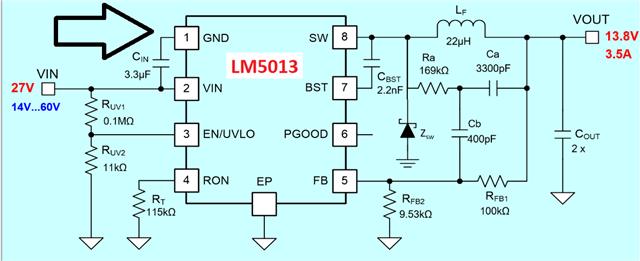
Other Parts Discussed in Thread: LMR51635, LM65645, LM5013-Q1, LM5013

Hi,

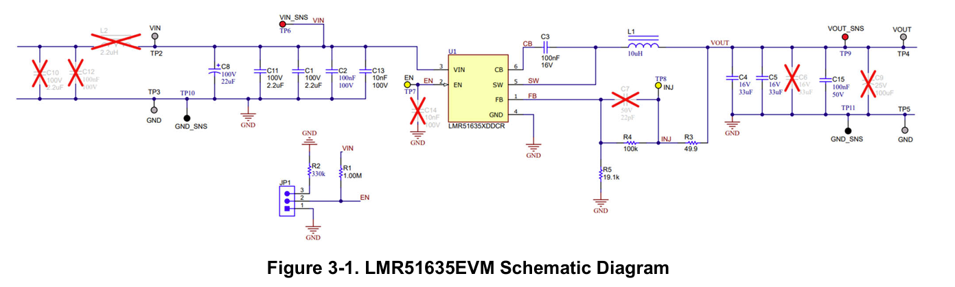
I am currently designing a custom board using the LMR51635, and I am referencing the LMR51635 Buck Evaluation Module design as a starting point. While reviewing the user guide (document SLUUCT3A), I noticed a discrepancy between the schematic and the Bill of Materials related to the output capacitors.

The schematic labels the output capacitors as 33 µF, whereas the BOM lists them as 22 µF (X7R, 25 V). I would like to ensure my design matches the components actually used on the official EVM.

Taking into consdieration that my VOUT is 13.8V not 5V.

Could you please confirm:

  1. For the Cout, what is the exact recommended part number in my VOUT case (13.8v)?

  2. For the inductance, what is the exact  recommend part number in my VOUT case (13.8v)?

Your clarification will help me ensure component accuracy and optimal regulator behavior in my application.

Thank you in advance for your time and support.


image.png

image.png

  • Hi Fawzy,

    Thanks for the query!

    Will get back to you as soon as possible.

    Thanks and Regards,

    Sourish Nandy.

  • Hi Fawzy,

    Just to confirm, Can you kindly state the operating conditions for you device? (eg: Nominal Input Voltage, Frequency, load current, etc.)

    Thanks and Regards,

    Sourish Nandy.

  • Hi Sourish,

    The nominal input voltage ranges from 18V to 50V, and the load current is approximately 1.5A.


    I’m not entirely sure which frequency you’re referring to, but I’d be happy to share the schematic with you privately.

    Thanks and Best Regards,

    Mohammed

  • Hello Fawzy,

    Thanks for the specifications!

    I was talking about the switching frequency which is dependent on the variant of IC you use as shown below in the table given in datasheet:

    I am assuming you are using the IC variant given in the EVM schematic diagram i.e; LMR51635XDDCR, so switching frequency is 400kHz.

    I will get back to you with the data you want as soon as possible.

    Thanks and Regards,

    Sourish Nandy.

  • Hello Fawzy,

    You can use the values in the filled up Quickstart calculator for your operating conditions.

    LMR51635 Quickstart Calculator_REVA.xlsm

    The inductor and capacitor values are taken such that it maintains a phase margin of above 45 degree and has ripple current within 45% limit.

    The output capacitor value used is after derating so use capacitor value accordingly.

    You can use output capacitors of X7R or X5R.

    You can use a 16uH standard inductor of your choice.

    Hope this resolves your query!

    Thanks and Regards,

    Sourish Nandy.

  • Hello Sourish,

    Could you please clarify the difference between the recommended and the actual values for Cin, Cout, and Lout?

    Best Regards,

    Mohammed

  • Hello Fawzy,

    The actual values should be as close to recommended value as possible.

    The Quickstart Calculator that I attached before has the recommended values for your conditions.

    For Cout value take care of the derating factor of the capacitor used.

    For inductor, take the saturation current of inductor around 3A (2*Load current) for proper operation.

    Thanks and Regards,

    Sourish Nandy.

  • Hello Sourish,

    Sorry for many questions, I know TI offers several buck regulators; could you recommend a different, higher-reliability part that can deliver up to 2.5 A (or better)? I’ve already selected a chip rated 3.5 A to give myself headroom for future functions and improved thermal margin, but I’d like your opinion on alternative parts (specific part numbers please) and the trade-offs for each — efficiency, thermal performance/derating, input range, switching frequency (and any audio-related EMI implications). My application is powering an audio → amplifier board, so low output ripple, good PSRR, and options for soft-start/pop mitigation are important; please call out any recommendations for filters or layout practices that help reduce audible switching artifacts.

    I appreciate your advice.

    Best regards,

    Mohammed

  • Hello Mohammed,

    Thanks for the queries!

    I will get back to you with the recommendations you asked for as soon as possible.

    Thanks and Regards,

    Sourish Nandy.

  • Hello Mohammed,

    You can check out the following 4 IC as an alternative to LMR51635:

    LM65645 has the provision for input filter too.

    This are some of the device that you may check out the datasheets of.

    You can check even more device on webench:

    Power Designer

    If you have any more questions, feel free to ask.

    Thanks and Regards,

    Sourish Nandy.

  • Hi Sourish,

    I decided to go with LM5013-Q1 and initially planned to follow the LM5013-Q1 EVM schematic. However, I’ve encountered some inconsistencies that make it difficult to move forward confidently:

    1. The BOM and schematic for the EVM do not match in capacitor values (specifically for C8 and C9).

    2. The SNVR514 — LM5013-Q1 Design Calculator shows a schematic where the GND pin is not connected to ground, which seems incorrect.

    I’m not trying to flag errors, but I’m building a large prototype board, and I want to avoid small yet costly design mistakes.

    Could you please point me to the most up-to-date and internally consistent reference (datasheet, EVM design, or validated schematic) that I can rely on for the LM5013 or LM5013-Q1?

    Your clarification would help restore confidence that I’m aligning with the correct TI design guidance.

    Best Regards,

    Mohammed 

  • Hello Mohammed, 

    I will get back to you as soon as possible. 

    Thanks and Regards, 

    Sourish Nandy. 

  • Hello Mohammed,

    I don't handle the device LM5013.

    So, can you kindly open a new e2e thread for the LM5013 so the concerned engineer can directly contact you?

    Hope I was able to answer your other queries until LM5013.

    Kindly click resolved on this thread so as to wrap it up here.

    Thanks for your consideration!

    Thanks and Regards,

    Sourish Nandy.