LP2980-N: The voltage drop issue of the output voltage of the LDO (Low Dropout Regulator) LP2980IM5X-5.0 on the main control board.

Part Number: LP2980-N


LDO LP2980IM5X-5.0 Voltage Drop Issue Report

The description of the current issue is as follows:

LDO in Use

Model: LP2980IM5X-5.0 /NOPB; Lot: 2025
 
  • 143 main control boards have malfunctions. The LDO supplies power to the memory chip, and the malfunction manifests as failure to save after program download.
  • The 5V output voltage drops to 1.2V–1.5V.

Application Scope

4 types of circuit boards, including:
 
  • 2 types of main control boards (with slightly higher load; hereinafter referred to as Main Control Board 1 and Main Control Board 2)
  • 2 types of signal boards (with lower load)

Background

  1. Usage Duration of LP2980IM5X-5.0: It has been used in bulk for over 3 years.
  2. Datasheet Update: On March 11, 2025, TI’s official website updated the technical data of this chip. The datasheet notes that the parameters of the "legacy chip" (old chip) and "new chip" differ.
  3. Past Usage History:
    • For Lot 2024 chips, over 12,000 units were used in the first half of the year, and all boards passed function tests.
  4. Current Issue Scope:
    • The problem occurs in boards produced after September, which use Lot 2025 new chips (approximately 600 units used so far).
      • 4.1 143 main control boards are malfunctioning: Abnormal Vout output at PIN5 (not in a stable state). Most Vout values measure between 1.2V–1.5V with a digital multimeter, while a small number show 5V.
      • 4.2 Over 200 signal boards have normal output.
  5. Summary: The Lot 2025 new chips show different performances across the 4 types of boards. A clear pattern is: Most main control boards (with higher load) are abnormal, while signal boards (with lower load) have normal output.

Root Cause Analysis & Questions

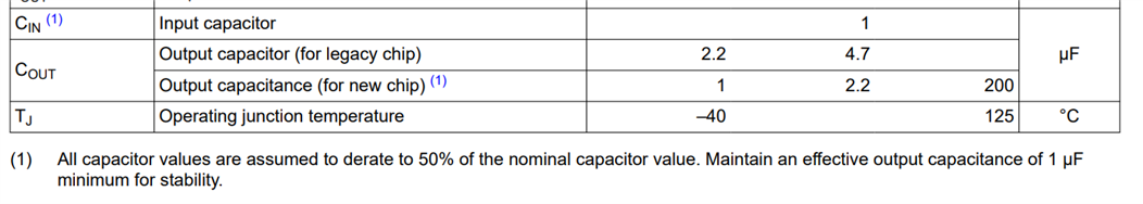
We have noted that the new datasheet specifies the following matching circuit requirements for the new chip:
 
  1. A 1uF capacitor for Vin, and a 2.2uF–4.7uF capacitor for Vout.
  2. The original design of the malfunctioning Main Control Board 1 was completed at least 5 years ago:
    • It uses a 100nF capacitor for Vin (smaller than the recommended 1uF).
    • It uses a 1uF capacitor for Vout (at the minimum of the recommended range).
 
Our questions are:
 
  1. Is the current abnormal Vout (voltage drop to 1.2V–1.5V) related to the smaller matching capacitor values?
  2. For Lot 2024 chips: Some have CCO origin "UK" (United Kingdom), others "USA" (United States), with different thicknesses of the silk screen font. Given the different origins, updated datasheet, and the distinction between "legacy chip" and "new chip" in the datasheet—do the required matching capacitor values for Vin and Vout differ between the two chip types?
  3. If the answer to Question 2 is "YES", could you provide a copy of the chip datasheet for 2024 and earlier? This will help us make a comparison.

Solutions Attempted for Voltage Drop

  1. For Main Control Board 1:
    • Replaced the 100nF Vin capacitor with a 1uF one.
    • Replaced the 1uF Vout capacitor with a 2.2uF one.
    • 6 modified boards have been tested with normal output; wider-range verification is pending.

Proposed Solutions to Be Attempted

  1. For Main Control Board 2:
    • The current board has no capacitor for Vin (cannot be replaced temporarily).
    • Plan to replace the 1uF Vout capacitor with a 2.2uF one; verification is pending.
 
Looking forward to your reply! Thank you for your support!
  • Hi Xiang,

    Thank you for the detailed information!

    The new chip can have issues with large, fast transients that previously worked on the old chip. Larger output capacitance and a larger decoupling capacitor at the load are good ways to help here. The root cause here seems to be that the current limiting loop (which is designed to pull the output below regulation when too much current is sourced) has been sped up significantly. Digital chips, like memory devices, tend to pulse their loads. The new chip can sometimes react to the initial larger transient current spikes before it has a chance to average out, temporarily bringing the output significantly below regulation. There also seems to be some increased sensitivity to ground loops in the new chip.

    In the above case, the waveform can look like an exponential decay downward in voltage until it rises back to regulation.

    Some other possible causes:

    There's a 1uF effective capacitance requirement for stability for the new chip, a 1uF nominal capacitor will not always meet this. The datasheet notes 50% derating as a rule of thumb. Stability issues can show up only after a transient, at after which they lock themselves into an oscillating state.

    There are also the usual causes for VOUT issues to be aware of: thermal limiting (device will overheat, shutdown, cool off and cycle: this will average out to below regulation) and dropout (high currents increasing the headroom requirement and bringing down input). But since the old chip worked, I do not think they are the likely cause.

    Questions:

    • Is it possible for you to get a scope shot of the issue with Vout? (Ideally VIN, IOUT, too)
    • What is the input voltage of the LDO?
    • Does the 1.2-1.5Vout persist after the failure observed?
    • When you mention not in a stable state, does that mean VOUT is not at a constant value in the 1.2V-1.5V but rather oscillating/changing within that range?

    To answer your questions directly:

    1. Is the current abnormal Vout (voltage drop to 1.2V–1.5V) related to the smaller matching capacitor values?

    The lower capacitance (relative to the new chips recommended range) likely exacerbates the transients, and increasing the output capacitor especially should help the issue.

    2. For Lot 2024 chips: Some have CCO origin "UK" (United Kingdom), others "USA" (United States), with different thicknesses of the silk screen font. Given the different origins, updated datasheet, and the distinction between "legacy chip" and "new chip" in the datasheet—do the required matching capacitor values for Vin and Vout differ between the two chip types?

    Yes. The new chip has an effective output capacitance and the legacy chip has an output capacitor requirement. There is also an ESR requirement in the new chip, but if you are using ceramic capacitors this should already be met. A 1uF nominal output capacitor is likely to guarantee that requirement is met over all operating conditions for the new chip.

    We are currently shipping both legacy and new chips, distinguished by CSO information on the packaging label. This should help identify whether they are the new chip vs legacy chip. We intend to eventually shift all flow to the new chip.

    3. If the answer to Question 2 is "YES", could you provide a copy of the chip datasheet for 2024 and earlier? This will help us make a comparison.

    The 2023 version still mentions legacy and new chips but the 2016 version predates it, which would you like?

    2016  Note: No mention of Cout requirements in Recommended Operating Conditions Table
    2023

    Suggestions:

    • Increasing output capacitance on the new chips significantly (to 10uF or higher). Increase decoupling capacitor at power rail at load.
      • Note: If it is the current limiting issue, then we have also seen cases where adding a bias load (resistor) helps a bit, as it is not crossing as many orders of magnitude from zero.
    • Get a scope shot of Vout (ideally VIN, IOUT as well) displaying the issue

    Best,

    Gregory Thompson