BQ500212A: Wireless Tx with BQ500212A and small coil

Part Number: BQ500212A


Good morning,

I want to make a wireless charger that will be used with this Tx coil from Würth electronic : 760308101105, the Rx will be 760308101208 also from Würth. I believe this is a non-standard coil for Qi charging and I used a reference design from TI to start with. Here is what I have:

image.png


image.png

image.png


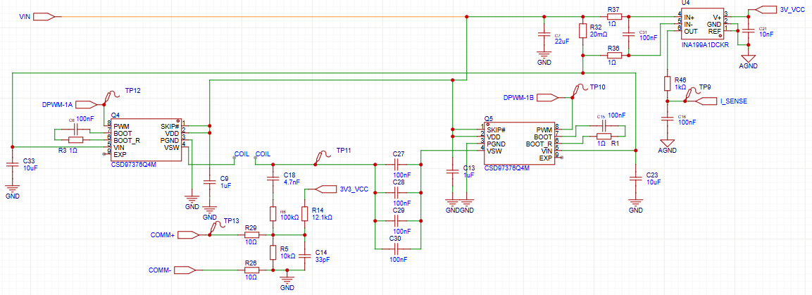
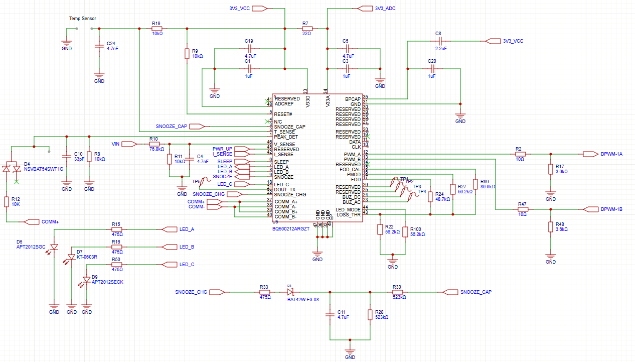
I have some questions about the different resistor and capacitor values I need to change so it works with this small coil.

  • I know that I need to change the capacitors C27-C30 to get a frequency ~150kHz
  • Does the FOD threshold need modifications?
  • Is there any other functionality that might need changes with the smaller coil?
  • Does this circuit seem adapted for the small coil overall?
  • I noticed some resistor values (in the part connected to usb) change between these two ref. designs, what do these depend on?
    • sluuap8
    • slvu928c
  • Hello

    The Wurth 760308101208 is a small 10mm coil, this is high risk.  This coil will have problems at start up due to low digital ping voltage.

    1.) I know that I need to change the capacitors C27-C30 to get a frequency ~150kHz-- Bill J - C27-C30 should be tuned to 100kHz will the TX coil L value

    2.) Does the FOD threshold need modifications? -- Bill J -- If you see an FOD fault then increase threshold

    3.) Is there any other functionality that might need changes with the smaller coil? -- Bill J -- this should be OK

    4.) Does this circuit seem adapted for the small coil overall? -- Bill J - if the coil L value is kept the same design should scale.

    5.) I noticed some resistor values (in the part connected to usb) change between these two ref. designs, what do these depend on? -- Bill J - OK to use sluuap8, without network.  Pull pin 45 to 3.3V.

    • sluuap8
    • slvu928c
  • Hello Bill, thank you for your response.

    - I tuned the capacitors to obtain 100kHz with the TX coil

    - Based my design on sluuap8, an wired pin 45 to 3V3_VCC

    I now have some questions regarding my layout/PCB design. Here is my current schematic (adapted sluuap8):

    My PCB layout is as follows.

    Top layer:

    It contains all the components, most of the traces, and a large part of AGND. FOD resistors placed on the border for easier tuning. 

    Inner layer 1:

    This layer is mainly AGND, components that I could not connect to the top layer AGND are connected to this layer through vias in the pads.

    Inner layer 2:

    It contains the remaining traces that I was not able to route on the top layer. Does not have a ground plane.

    VIN follows the drawing in red, 3V3_VCC in blue, COMM+/- in purple and the DPWM-1A/B in yellow.

    Bottom layer:

    It contains the GND plane, components that need it are connected through vias. The GND plane is connected to AGND with a single 0Ohm resistor.

    My questions are:
    - Is it okay to have AGND on two layers, and linked with suture vias?

    - Should the VIN, 3V3_VCC and DPWM traces be shorter, or can it work fine this way?

    - All the traces have a width of 10mil. Does any trace (or all) need to be thicker?

    - Does the layout seem okay, or am I missing something obvious?

    PS. I know that the Qi standard requires specific types of coils, and tuning capacitors to be 400nF. However I do not need it to be Qi certified and I'm okay with lower efficiency due to the smaller coils I would like to use.

  • Hello

    My questions are:
    - Is it okay to have AGND on two layers, and linked with suture vias?  --- Yes this will be OK

    - Should the VIN, 3V3_VCC and DPWM traces be shorter, or can it work fine this way?  -- They are low current and should not be a problem.

    - All the traces have a width of 10mil. Does any trace (or all) need to be thicker?  -- Only the power traces

    - Does the layout seem okay, or am I missing something obvious? -- Recommend using larger traces on the power section.  Trace into Q1 and Q5 and out of Q1 and Q5.