This thread has been locked.

If you have a related question, please click the "Ask a related question" button in the top right corner. The newly created question will be automatically linked to this question.

TPS54620 does not regulate

Other Parts Discussed in Thread: TPS54620

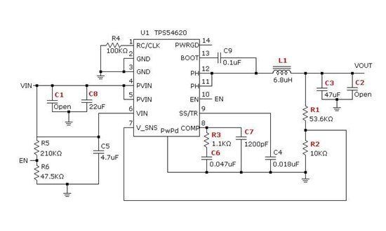
Dear colleagues, I'm having several problems with this DCDC converter. With the circuit of the picture (SwitcherPro) I have the follwing problems (Vin=12V, target Vout=5V)

1 - With this resistor devider for the EN pin I don't get to set more than 1.05V into the pin. The only way to set it is directly from a external source (1.5V for example).

2 - Once the EN pin has more than 1.3V the output is still not regulated. Just shows 0.344V. Vsense rises slowly (seconds) to 0.2V.

3 - If I increment Vin to 15V, Vsense goes to 0.75V but Vout is still 0.344V.

It makes no sense to me. Could you please give me some tips to clarify this problem?

Thanks,

  • That EN resistor divider network should have over 2 V at Vin = 12 V.  Is SS/TR pin being totally discharged at start up?  Try adding 1 megohm in parallel with C4.  If that does not fix theproblem please post waveforms.

  • Hello, the EN resistor divider network is already set to have more than 2V at Vin= 12V, nevertheless,  at EN pin  there is no more than 1.05V, this is because the EN pin is being pulled down internally.

    The SS/TR pin is totally dischargued at start up and during the start up it remains dischargued. It is never charging, just when I set with an external source 2V into the EN pin and I increase VIN to 15 or 16V, the SS/TR pin charges up to 0.75V but this is a forced behaviour that I would not like to consider.

    I think the problem is the internal pulling down of EN pin.

    What do you think? Thanks a lot!

  • How many boards out of how many total exhibit this problem?  If it is only one or two, you may have some workmanship issues, or possibly the IC is damaged.  Try to remove the UVLO resistors completely and see if the circuit starts on its own (there is an internal UVLO).  Look for any external contamination that may be holding EN low.  Lastly you can replace the IC.

  • This is the third board that shows this behaviour, in the first one the IC was replaced and the regulation is "more or less" ok (I say "more or less" because the voltage in Vsense is 0.65V instead of 0.8 and I had to vary the resistor divider in Vout in order to get 5V). The other 2 boards have the same behaviour. In one of them I have changed de IC and I still see the same behaviour.

    Originally the EN pin had no UVLO resistors and it does not work and that is why I put the UVLO resistors at Vin but nothing! It's very weird that every IC is damaged, and more when they all are not from the same "pack" or "order".

  • If the VSENSE voltage goes to ~ 0.65 V, then the IC is damaged.  There is a known issue where the device can be damaged during rework.  Sometimes hand solder process can cause the VSENSE pin to exceed the absolute maximum voltage rating. I beleive there is an update in progress to make the devices immune to this type of overstress, but let me state again, that it is caused by exceeding the absolute maximum rating for the device, so the device is not technically at fault here.


    As to the UVLO issue,  I have not seen that before.  I am still inclined to beleive it may be damaged by process issues, but I could be wrong.  You need to ensure that the SS/TR voltage is fully discharged.  It has to be below about 20 mV, so you have to check it closely.  If you can provide waveforms, I may be able to tell more.  Any of the key circuit operating ponts.  Make sure to include the PH signal in each plot.  take both long time scale (500 usec/div) and zoomed in views (1 usec/div) or any other timescale that shows behaviour that looks abnormal.   If you have one of the ICs that shows the low UVLO condition, you should contact your local AFA or FAE and have them submit the part for failure analysis.

  • hi Daniel,

       i met the same trouble like you, the tps54620 doesn't work, no pwm wave output. could you tell me how  to  sorve  it?

    thanks a lot

  • Hi,

    The problem on this chip is basically that it is very susceptible to soldering temperature. I finally had to replace IC several times sugesting to workman not to apply excesive heat onto leads. Using thermal glue is also an option although, sincerely, I would definetely choose another IC from Texas for this same purpose. Not QFN please.

  • The IC was updated a couple years ago to prevent the rework issue from occurring. If you are having start up problems, it is likely something else. Can you post details about your issue?
  • Hi Jone,
    I have two boards with the same schematic now, which of them equiped with a tps54620 to provide +1.0V voltage for c6678 and another one provide +1.0v voltage for FPGA, and one of the two boards works all fine. But in the other board, the one that surpply power for FPGA works nomally, and the one surpply power for DSP can not generate PWM wave, and the voltage on SS/TR pin is 0. Then i shorted the +1.0V of FPGA's power supply and the DSP's , the boards works fine. The part of the +1.0V power surpply of DSP and FPGA are both the same. I checked the registance of the pins of tps54620 that works for DSP, and found nothing unnormal, then i have to exchange the chip for at least 4 times until it works fine.