


Part Number: LM5185
Hi,
I'm designing an isolated power supply with the LM5185 controller IC and would like to ask TI's opinion about my transformer selection.
- PSU main parameters are:
- input 16-28 VDC
- output 36 VDC, 0.5 A
- galvanic isolation between input & output
Here are screenshots from the LM5185 design calculator worksheet:
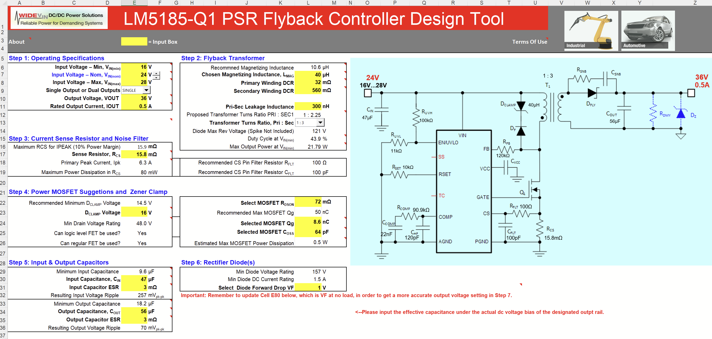
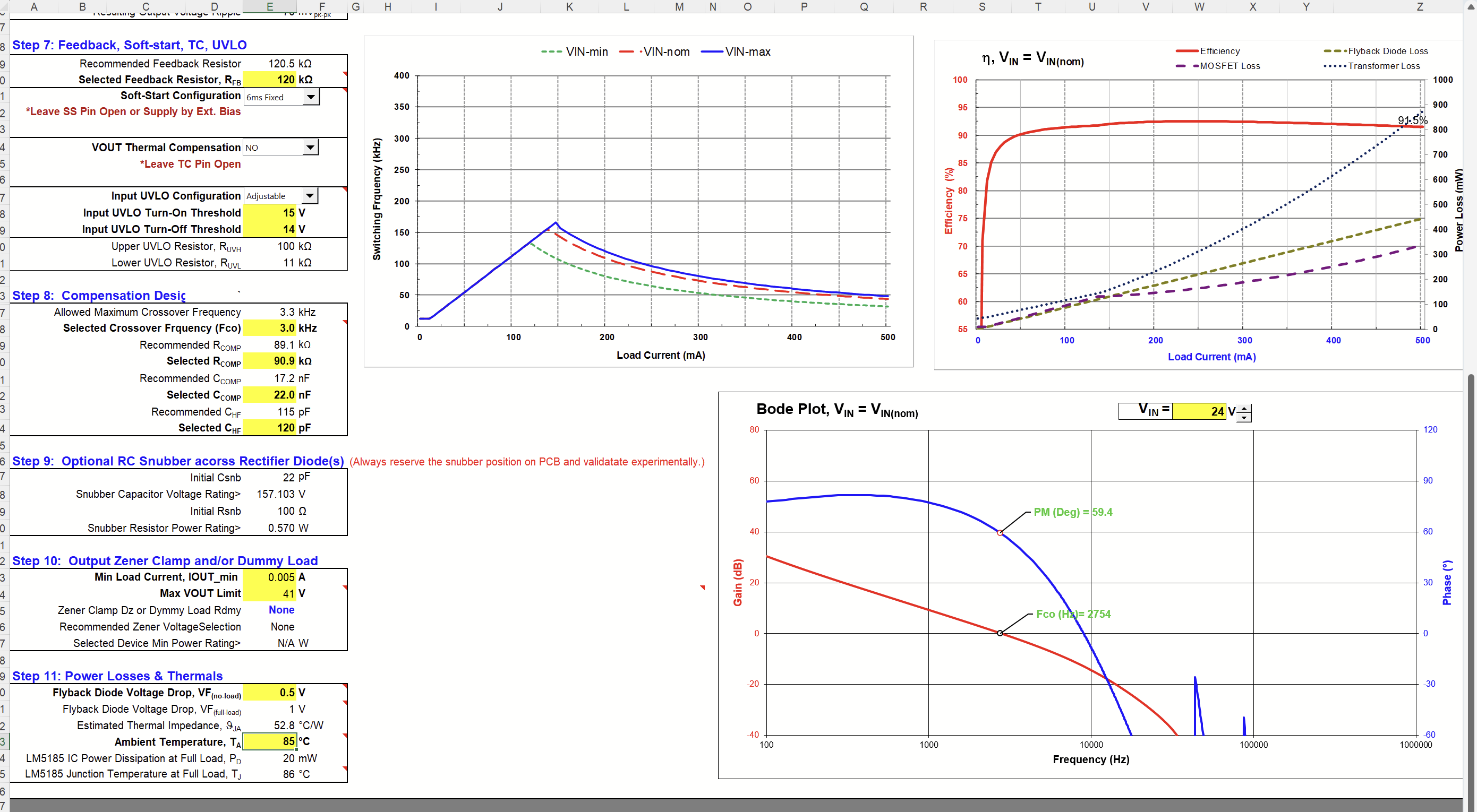
I used the LM5185-DESIGN-CALC.xlsx worksheet to simulate the following transformer:

I'm intending to use the transformer with its primary windings connected in series. The windings ratio would then be 2:6 = 1:3. With series-connected windings, the total inductance would rise up to 10µH*2^2=40µH, four times higher than the recommended inductance of 10.6µH.
My questions:
- Do you think this transformer would be oversized for this application?
- What are the disadvantages of using a transformer with higher than recommended primary inductance?
Thanks in advance!
