This thread has been locked.

If you have a related question, please click the "Ask a related question" button in the top right corner. The newly created question will be automatically linked to this question.

UCC21331: High Side DC Motor Control

Part Number: UCC21331

Hello


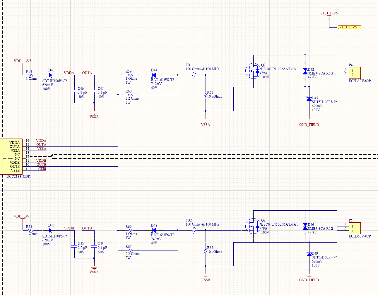
Am I missing anything for the below schematic?

  • High side switching brushed DC motor (diaphragm pump) - L = 10 mH, IPeak = 7A
  • PWM duty cycle between 1-10% @ 10 kHz
  • HV link voltage is 12V


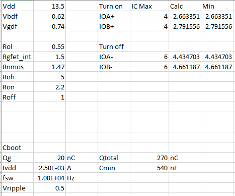
xls.PNG

  • Hi Robert,

    Are C47 and C53 capacitors supposed to be additional small decoupling capacitors for VDD - VSS? They are connected to the OUTA and OUTB nets so just want to confirm.

    Aside from that, there is nothing that sticks out as unusual here.

    I would highly recommend to utilize the schematic and layout design guidelines recently added to the product page under "Design & Development":

    This will have a complete checklist for all components that we recommend in a typical application.

    Regards,

    Hiroki

  • Should be in parallel with Cboot not between OUTA and VSSA, thanks.

    Yes, I followed the checklist and will follow the reference layout.  

    One question I have is about Dclamp: Instead of placing steering diodes on OUTA/OUTB, is it OK to add a bidirectional TVS after the ferrite to protect the FET gate and UCC21331 output driver?  I cannot sink much power to the positive rail.  

    Thank you

  • Hi Robert,

    I don't see an issue with using a bidirectional TVS to protect the FET gate as long as the voltage ratings are selected to fit the gate drive voltage.

    Unfortunately I cannot find any reference designs using this method as this is not too common.

    Regards,

    Hiroki