This thread has been locked.

If you have a related question, please click the "Ask a related question" button in the top right corner. The newly created question will be automatically linked to this question.

BQ2000 MTO clock frequency vs actual time out

Other Parts Discussed in Thread: BQ2000

HI All,

I have been having a bit of strain with a BQ2000 deisgn where it terminates early (NiMH 20 cell stack) and eventually treid a longer MTO period than I calculated - and bingo it works. It was terminating in the order of 2.5 times faster and not very accurately time wise - with the latter in mind - might I be backing up the wrong tree with it?

My question - is there a number of MTO pin oscillations which = the MTO period - so I can look at what is going on - the datasheet only gives a formula for R, C to minutes timeout!

I'd be very pleased for your input!

Regards,

Dave

  • Dave,

     The charge termination happen under two conditions:

    •  Maximum charge time =1MTO
    • Peak Voltage

     If the peak voltage happens first, then the termination will happen before MTO. VBAT should always be less than VMCV for NiMH battery type. Also, The timer can be paused if VTS>VLTF.

     Tahar

  • OK Thanks for that  - however - I am seeing (logged Vbat plotted) no Peak, until I extended the MTO a considerable amount - so I wanted to check my MTO timing directly rather than via the data. So would love a relationship between fMTO pin and MTO in minutes as per the data!

    Thanks

  • Dave,

    The RC pin contains valuable information in determining what state the bq2000 is in:

    •  If the RC pin is low (around VSS potential), the IC is in sleep mode.
    •  If the RC pin is low for brief instants during fast charge, the bq2000 is sampling the BAT pin for PVD.
    •  If the RC pin is at some DC value (usually around 1-2V), then the IC has paused the timer or the timer is inactive.
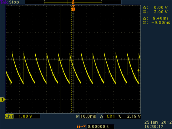
    •  If the RC pin is a sawtooth waveform (similar to Figure 15), then the timer is running and the RC pin is considered “active.”
    •  Lastly, the RC pin can be  loaded by too large of a C or too small of an R. This will sometimes make the usual sawtooth waveform look like a triangle waveform on an oscilloscope (the rise time is lengthened), or the RC signal could have the appearance of being clipped (flat top or bottom). The timer will be unreliable under these conditions and the bq2000 should not be operated in this manner.

     Table 2 on the DS summarizes the different states of the RC pin.

    What are the RC & MOD pins status?

      Tahar

  • Hi,

    Yes both pins are active until it stops, I done have a scope free to see what happens then - but it appears to be pulsing MOD every now and then - which I took to be top up.

    RC pin is the proper saw tooth!

    Dave

  • Hi Golan,

     MOD pin is turned OFF & ON at rate MTO/128 for sampling the BAT pin and check for the PVD. By looking at pulses on the MOD pin you can figure out the set MTO time.  

     What is the status of LED pin?

     Once you get your scope free, please send me some scope plot to look at. I need to see:  RC, MOD, TS, BAT.

     In the mean time, you can play with R&C values. What are the values of R and C? You may have too large C and too small R.

     Tahar   


  • Hi Tahar,

    Right - I will split some of the info un in various posts so as not to make it too massive:

    I have timed the MOD pin gaps,

    Good channel - 5m56s => MTO is 12.6hours - I have 0.72A going into biggest battery - 3.2Ah so this is WAY too long. But it works and PVD perfectly in all my trials.

    Bad Channel : 2m21s => MTO is 5 hours - probably a wee bit short I think.

    LED pin is ON until it terminates.

    Good R=47K C =470n

    Bad R=18K C=470n.

    TS is disabled - DC 2V where VCC = 5V.

    Scope traces to follow...

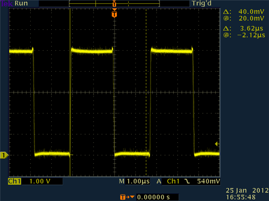
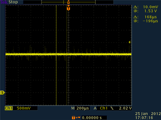
  • BAD channel:

    MOD :

    BAT pin:

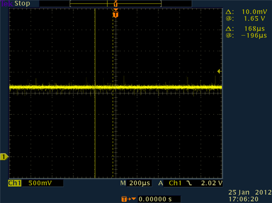
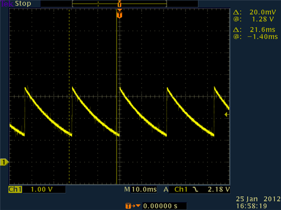
    RC pin:

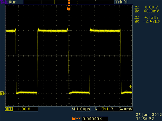
  • GOOD channel:

    MOD pin:

    BAT Pin:

    RC pin:

  • Dave,

     Thank you for porviding these plots. I do not see anything obvious wrong  with the timers by just looking at the plots you provided, I need to do some measurement in the lab to our EVM to confirm that the timers is operating properly with your RC values.

     However, the typical charging rate for the NiMH battery chemistry is C/2 or larger. I see in the post that 0.72A is used out of 3.2A. Can you do the same test  with at  least C/2 charging current (around 3 A ) and then see if that is not the cause of the issue. Is there any load as you charge the battery? becuase any changes in the load will cause termaniation

     Please find the SLVA166 application note for more detail about the possible termination issues for the NiMH.    

     I will updated with my findings in the lab…


  • Hi Tahar,

    Thanks for that, no there is not a load connected - just the battery. I am aware of the C/2 suggestion, unfortunately this unit contains 10 chargers - so there are issues with the total current becoming excessive.

    Not sure if I can make one channel to say 3A just to try it or not with the driver transisitor I have... will have a look!

  • Dave,

     The attached is the RC pin with different MTO’s. I don’t think the issue you are experiencing is related to the timer. I think that there are other factors that cause the IC to terminate. Can you please send me your schematic to look at? Did you compare it with the EVM schematic?

     -Tahar


    Time vs RC frequency.xlsx