This thread has been locked.

If you have a related question, please click the "Ask a related question" button in the top right corner. The newly created question will be automatically linked to this question.

TPS25751: Extend Power Capacity

Part Number: TPS25751
Other Parts Discussed in Thread: TI-PD-ANALYZER

Dear Texas Instruments Support Team, 

Please find attached the block diagram of our current development:

TPS25751 Block Diadram_4.png


TPS25751 Schematic.jpg

Our main goal is to allow simultaneous charging and data transfer via the same USB Type-C port on the host side. We chose the PD controller based on your suggestion, and it works well. Now, we're increasing the charging power capacity. We conducted tests by loading various patch bundle images into the EEPROM, and here are the results.


image.png

In our experiment, we used a fixed voltage power source on PPHV pin for testing.
From our findings:
- A 20V fixed voltage external power supply can fast charge a laptop and MacBook, but not an iPad.
- A 15V fixed voltage external power supply can fast charge an iPad and MacBook, but not a laptop.

We aim to enable fast charging for iPads, MacBooks, and any laptops using the TPS25751D PD controller.

Please advise on how to meet our requirements.

Should we use a variable voltage power supply connected to the PPHV pin? If so, what should the base voltage be for adjustments? Is there a way to control this variable voltage power source?

Your insights on these points are critical for our design decisions. We sincerely appreciate your continued support and look forward to your expert recommendations.

Best regards,
Mayank Mirajkar

  • Hello Mayank,

    Please give me till the end of day tomorrow to respond. Thank you for your patience and understanding.

    Bests,

    Katilynn

  • Hello Mayank, 

    Thank you for your patience in my support. 

    I understand the goal is to support fast charging for the iPad, MacBook, and any laptop using the TPS25751D.

    I see that the configuration you tested has two PDOs configured. Have you done any testing with all three PDOs (PDO1=5V3A, PD2=15V.4.5A PDO3= 20V/4.5A) configured? I am curious to see if the reason we do not see all devices capable of fast charging is due to the power ratings of the sinking device (ie. iPad/Laptop).

    Can you provide me with the two .JSON configuration files used in the testing described above? This will allow me to confirm the configuration is set up correctly for your design needs.

    Additionally, can you provide me with the USB PD data on the CC1 and CC2 channels that shows the communication between the source and sink devices? This can be done using a TI-PD-ANALYZER Evaluation board | TI.com.

    Thank you,

    Katilynn

  • Dear Texas Instruments Support Team, 


    Can you provide me with the two .JSON configuration files used in the testing described above?

    Attached are the .JSON files for my configuration as requested:
     /cfs-file/__key/communityserver-discussions-components-files/196/Test_5F00_WebUI.rar


    Following your suggestions, I implemented the configuration, but it did not yield the expected results.


    I would like to configure the GPIO pin of the TPS25751D PD controller as follows:

    • When PDO2 is configured, GPIO_1 should be high, and all others should be low.
    • When PDO3 is configured, GPIO_2 should be high, and all others should be low.

    I tested this with the JSON configuration, but it did not meet my requirements.

    /cfs-file/__key/communityserver-discussions-components-files/196/tested_5F00_GOIP_5F00_config.rar

    Additionally, can you provide me with the USB PD data on the CC1 and CC2 channels that shows the communication between the source and sink devices?


    We have not Ti-PD-Analyzer so not test on CC pin. I try on logic anayzer but it not give proper result.

    Could you please provide detailed guidance on:

    • How to configure any GPIO pin of the TPS25751D PD controller?
    • Is there another method to determine which PDO is active: PDO1, PDO2, or PDO3?


    Your insights on these points are critical for our design decisions. We sincerely appreciate your continued support and look forward to your expert recommendations.

    Best regards,
    Mayank Mirajkar

  • Hello Mayank,

    Thank you for providing me with the configuration files you used for testing. 

    Following your suggestions, I implemented the configuration, but it did not yield the expected results.

    Could you please provide a detailed explanation of the specific results you are expecting to achieve? As I understand it, your goal is to have the iPad and laptop accept a fast-charging contract. However, I would like to clarify whether the 12V contract for the iPad and the 20V contract for the laptop do not meet your requirements for fast charging.

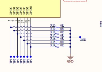
    Additionally, looking at this picture below I see the GPIO pins are tied to GND. For the GPIO event you will need an external pull-up/down when the PD is in PTCH mode if you want to see this GPIO event assert.

    With this in mind, I will recreate the GPIO configuration on my end and will get back to you by end of day Monday with next steps/possible causes.  

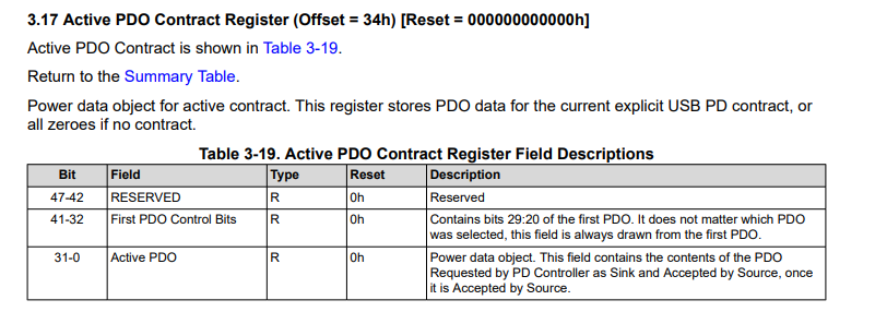
    Is there another method to determine which PDO is active: PDO1, PDO2, or PDO3?

    See register 0x34 Active PDO contract:

    Thank you,

    Katilynn