This thread has been locked.

If you have a related question, please click the "Ask a related question" button in the top right corner. The newly created question will be automatically linked to this question.

LM5177: LM5177EVM - IMON Defect

Part Number: LM5177

Dear,

I was testing the LM5177EVM-HP module to see if the design was applicable with modifications for our application. I initially tested in the default setup which worked fine. 

Two modifications were made:
- Feedback resistors altered to create 24V output
- Current sense resistor halved to increase the allowed inrush current for our output

At this point, the setup was functional. However, further steps were taken to implement the current limiting behavior.

IMONOUT jumper was changed from VCC to floating (added RC of 510 Ohm and 2.2nF) 
CFG was set to nr 6 (DRSS enabled, HICCUP disabled, PSM 10% and Current limit enabled)

Other settings:
SYNC - VCC
MODE - VCC

When activating the supply, the test board got permanently damaged (25V input and without a load connected).

When reverting the IMONOUT jumper to VCC and CFG back to the prior setting without the current limit enabled, the board no longer generated an output.

This test was repeated with a second board to see if soldering errors were made, but the same issue occured. 
(In addition, this second time, components R42, R43 and C30 were set to 100 Ohm, 100 Ohm and 100pF instead of the original 0 Ohm resistors, to see if this had an impact)
When activating the supply, the board heated up to around 70 degrees before I turned off the supply. When reverting everything to the original state, no output or switching behavior is visible.

After further testing, it turns out that the in- and output are shorted on one of the test boards, and just the output on the other. After removing capacitors, ... to pinpoint the cause, it turns out the switching MOSFETS are the ones that are shorted (VDS is 0 Ohm and VGS of 10 Ohm). This is true for all the MOSFETS on the first board and Q2, Q3 and Q4 for the second.

Do you have any idea what could cause this defect?

If it is related to the values of the RC or input components of ISNSP/ISNSN would it then be possible to provide some suggested values for these to limit the output current to 400mA? (24V output, original input range/frequency)

  • Hello Robin,

    I am very sorry that you have issues with the EVM. Could you please use the Quickstart calculator to calculate the necessary changes for your specific requirements? SNVR519 Calculation tool | TI.com

    BTW, I would as well recommend using the LM51770 instead of LM5177. This would mean exchanging the IC on the released EVM or using the LM51770EVM-HV Evaluation board | TI.com and the calculator https://www.ti.com/tool/download/LM51770-QUICKSTART-CALC

    The MOSFETs used on the LM5177EVM-HP are 40V MOSFETs. Possibly your changes caused overvoltage on the input or output damaging them.

    Best regards,
    Brigitte

  • Hello Brigitte,

    Thank you for the swift response.

    I have been working with the LM5177EVM, as it was what was available to me at the time, and I do plan to use the LM51770 for the final design. Based on the datasheets, I assume that if the LM5177 setup works, the LM51770 can simply be used as a drop-in replacement on the same PCB. Please let me know if that assumption is incorrect.

    However, I would like to resolve (or at least understand) the issue before implementing the IC into a prototype, as I currently have no clear explanation for why the board was destroyed.

    I plugged my values into the suggested calculator tool and found that my R/C IMON values were slightly off, and the RSLOPE value was no longer optimal. Could these deviations cause an overvoltage condition on the MOSFETs?

    - RSLOPE (used): 68k (suggested): 133k
    - C IMON (used): 2200p (suggested): 200p
    - R IMON(used): 510 (suggested): 2.4k

    Changing these values does not seem to influence the stability of the design in the calculator though and I followed the steps in the development board user manual when converting to current-limiting mode, so I am quite confused as to how such a severe and consistent instability could have arisen.

    As I mentioned earlied, the board was working perfectly fine, but only when current limiting was enabled, the damage occured. Does this setting or the values influence the stability to this degree? Could it be related to the interaction between the power save mode (PSM) and the current limit that falls below this threshold?

    Thank you for your help.

  • Hello Robin,

    Sorry for the late response. I am confused as I thought I already answered your request.

    Without measurements about the issue, it is highly speculative on what could have caused the issue you observed.

    I expect you either had oscillations on VIN or VOUT causing overvoltage, damaging the MOSFETs.

    I can have a look at the calculator to dig more into the details, but then please share it setup with all the changes you did to the EVM and the input voltage you tested it with.

    Best regards,
    Brigitte

  • Hello Birgitte,

    I had the follow-up question because the calculator results look fine to me and has nothing that seems to indicate instability. I would appreciate it if you could rerun the numbers, perhaps I am interpreting something wrong.

    Deviations from the original EVM:
    - Feedback voltage divider altered to 200kOhm / 8.66kOhm for a 24.1V output
    - Current sense resistor changed to 0.667mOhm (for a test prior to the one that failed, was not reverted)
    - Changed IMONOUT  circuit to 510 Ohm and 2.2nF (jumper removed)
    - CFG set to position 6
    - SYNC tied to VCC
    - MODE tied VCC

    I know 510 Ohm and 2.2nF are not optimal, but they don't seem to have any impact in the calculator tool regardless.

    I supplied the device with 25V at the input and nothing was connected to the output.

    Kind regards,

    Robin.

  • Hello Robin,

    For this test I will need some time. Please give me until next week.

    Best regards,
    Brigitte

  • Hello Robin,

    I reworked a board and checked your setup in the lab. The power supply works as expected and does not get damaged.

    BTW, I recommend using CFG=2 instead of CFG=6. If you set it to 6, you enable the current limiter, but then you should have just a resistor on the IMONOUT pin.

    Best regards,
    Brigitte

  • Dear Brigitte,

    The LM5177 datasheet specifies that it does need a RC compensation network for current limit operation:

    And I am looking to limit the current to roughly 400mA. Could you suggest some values for the RC compensation that would be suitable? Perhaps the ones you used for testing?

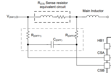
    In addition, the datasheet suggests a Rdiff / Cdiff filter for the peak current sense circuit with values around 10 Ohm and 180pF but never mentions the dimensioning for the ISNSP/ISNSN lines. However since the evaluation board includes 0ohm resistors and an option for a capacitor I assume that they should be placed here too. The evaluation board deviates from the suggested values by quite a bit though (100 Ohm and 100 pF)... It even suggests 100 nF for the cap in the ISNSP/ISNSN filter.

    Since the calculation Excel also does not mention the dimensioning, could you shed some light on how to find decent values, or share a set of good values for my 400mA setup? Or can I simply connect them to the sense resistor without this differential filter?

    Kind regards.

  • Hello Robin,

    Sorry, you are right, for the current limiter an RC network is necessary.

    But the reworked EVM is working if I am using CFG 2 or CFG 6. No damage happened with your setup on my reworked EVM.

    The ones I used for testing are the ones you mentioned in the thread above where you listed the changes. I am using the calculator to calculate the external components for the device, including the IMONOUT components.

    The filter on the ISNSx lines is dependent on the layout and therefore are hard to define upfront. We recommend having the components there if needed, but if the layout is very good and the sense resistor is placed in the middle of the output capacitors it can work as well without this filter. The signal on the ISNSx pins is mostly DC, so the filter is just there for filtering noise due to layout.

    Best regards,
    Brigitte

  • Okay so to double check your setup:

    JP1: MODE - VCC
    JP2: SYNC - VCC
    JP3: DTRK - GND
    JP4: Vin
    JP5: No jumper
    JP7: No jumper
    JP8: No jumper
    JP9: No jumper
    JP10: No jumper
    JP11: No jumper
    S1: switch 6 active

    Feedback resistors altered to create 24V output (I used 200 kOhm and 8.66 kOhm)

    R17 and R18 replaced by:
    - C IMON: 2200 pF
    - R IMON: 510 Ohm

    No input filter (0 Ohm resistors on ISNSP / ISNSN)

    25V supply 

    No added load

    No other modifications

    This is correct? If so I will retry to run the experiment like this to see if a mistake was made during the initial conversions after all.

  • Hello Robin,

    Yes, this is correct.

    Best regards,
    Brigitte

  • Dear Brigitte,

    I have tried again using the calculator and a set of very safe RC values for IMONOUT, and the setup now works. So thank you for the help so far! However, I was testing a few different configurations and noted that the power save mode (PSM) seems to disable my current limit.

    Without PSM (MODE connected to VCC) the current limit works and limits to 100mA.

    With PSM (MODE connected to GND) the current limit does not work and current is 162mA.

    Setup (default EVM board with the following modifications):

    - 500mOhm average current limiting resistor (100mA limit)
    - IMONOUT RC: 1kOhm, 18nF
    - Configuration: 5 / 14 (tried both, same outcome)
    - 100 Ohm load

    Expected output voltage 10V (100mA * 100 Ohm), measured with PSM disabled

    Actual output voltage 16.2V with PSM enabled.

    Does the PSM influence the current limit in some way?

    Kind regards,

    Robin.

  • Hi Robin,

    Thanks for the information.

    I will come back to you within this week.

    Best Regards,

    Hassan 

  • Hello Hassan,

    Thank you for taking a look at it.

    Kind regards,

    Robin.

  • Hello Robin,

    The current limit you are setting for average current seems to be lower than the power safe mode peak current limit of 10% or 15% of the peak current limit. The average current limit is averaging the current for several cycles before limiting it, but if PSM is enabled, I expect that the converter is just switching one or a few cycles to deliver the 100mA you set.

    Can you reduce the peak current limit for this test?

    Best regards,
    Brigitte

  • Hello Brigitte,

    The current limit I am setting is indeed below 10% of the peak current limit (default 1.33 mOhm equivalent resistor). Therefore I would expect PSM to be active, as well as my 100mA limit.

    However, in reality, when I enable both PSM and average current limit, the average current limit is ignored (continuous 162mA at the output, not a momentary transition but steady output)

    So when PSM is enabled, the converter does switch once every few cycles, but does not respect the 100mA limit.

    Without PSM (only average current limit active), the current limit does function.

    So while I do believe that reducing the peak current limit will fix the issue (since PSM will become inactive due to the current then being above 10% of peak), it does not help me for my setup as I want both the current limit and PSM to be active at the same time.

    Do you know if PSM and current limit are mutually exclusive?

    Kind regards,

    Robin.

  • Hello Robin,

    When PSM is enabled, the converter is not able to get a correct measurement on the output current as it averages over several cycles. So the amount of energy you are getting on the output can be higher than what you want to get as the average level is not aligned with the PSM cycles.

    They are not mutually exclusive as far as I know, but I will check to be 100% sure.

    Maybe a compromise can be found like a lower peak current limit while the average shall be such low?

    Best regards,
    Brigitte

  • Hello Brigitte,

    I don't fully understand your suggestion. Say I lower my peak current limit to say 500mA, then this would mean that my average current limit of 100mA now falls outside of the PSM region (0-50mA). So while my current limit will work, the converter will be rather inefficient as the controller and switching without power save mode consume roughly as much as my output load would.

    Or do you simply suggest to get the peak lower, but such that my average limit still falls within the PSM region (say 100mA being 12% while the threshold is set to 15%). So a 833mA peak current for example?

    Or if the influence of the PSM on the average current measurement is fixed, say 100mA * X, should I then reduce the average current limit with that factor X such that the result is once again 100mA? (Compensating for the current measurement error X caused by PSM)

    Could you please elaborate on this, perhaps suggest the peak current you would implement as a test?

    Kind regards,

    Robin.

  • Hello Robin,

    If you want to reduce the power consumption of the converter, in the standard use case, I think a reduction in switching frequency would make more sense than using the PSM. The PSM is used for reducing the power consumption for low load, if the maximum load is a lot higher than the standard load.

    So I think reducing the peak current capability to a value that fits to your needs for the maximum power you want to have at the output and reducing the switching frequency to reduce switching losses could be the right way to go.

    But as I do not know all the use cases you want to cover with one design, I am possibly wrong with my suggestions.

    Best regards,
    Brigitte

  • Hello Brigitte,

    Thank you for the suggestion, I am indeed looking for a high efficiency design at low power (current limit 400mA, but I am testing with 100mA at the moment).

    While reducing the frequency sounds promising, the datasheet states a minimum frequency of 100kHz. When entering this in the calculator in addition to a lower peak, this would require an inductor that is 150x my current value. In addition, I think the PSM pushes the frequency even lower than this, so the losses will likely still be higher.

    Preferably I would have maintained my used inductor and other components as I have multiple converters on the same PCB with different goals, which is why I was looking at the power save mode instead. The other design works properly at 100mA load with PSM enabled but without the average current limit, which is why I was hoping that it would still work with the limit set.
    It also works at 100mA with the average current limit and with PSM disabled. I am not able to get the latter to work with PSM enabled.

    So while I understand your suggestion, are you also implying that PSM will not work with the current limit function then?

    Kind regards,

    Robin.

  • Hello Robin,

    Can you please share an inductor current measurement of a measurement of the switch nodes when the device operates in current limit, but does deliver more output current?

    Can you please check the maximum current you can get on the output in PSM?

    Best regards,
    Brigitte

  • Hello Brigitte,

    I have tried decreasing the load to 50 Ohms, 33 Ohms and 2 Ohms, and none of them seemed to have their current limited while PSM was enabled. Without PSM they all resulted in the set 100mA.

    Would it be possible for you to modify your test setup from a few weeks ago and confirm that PSM and the average current limit are in fact mutually exclusive?

    Kind regards,

    Robin.

  • Hello Robin,

    Your observation is correct. I was not aware of this feature, but the average current limit is unavailable when the device operates in PSM.

    Best regards,
    Brigitte