This thread has been locked.

If you have a related question, please click the "Ask a related question" button in the top right corner. The newly created question will be automatically linked to this question.

TUSB1142EVM: CC Pins Inversion

  • Hi Moritz,

    I will double check, but I believe the current part being used on this EVM is the 2SK209-Y_TE85L,F_ , which is an N-Channel JFET.  I would recommend following what the top E2E recommends and using an N-Channel MOSFET.

    Thanks,

    Ryan

  • Hi Ryan, 

    thank you for checking.

    If it is confirmed could you add a comment to the first that the JFET is intentional. 

    Kind regards

    Moritz

  • Hi Moritz,

    The intention is for N-Channel MOSFETs to be used. I don't believe the creator of the EVM intended for these to be N-Channel JFETs and used these by mistake, though the EVM still works even with them implemented.

    Unfortunately, I cannot go back and edit the first thread, as it has been closed.

    Thanks,

    Ryan

  • Hi Ryan, 

    thank you for the update. But this means the 2nd Posting is incorrect right?

    So in summary if I connect CC1 and CC2 directly as intended, I won't need an inverter. 

    Kind regards

    Moritz

  • Hi Moritz,

    So in summary if I connect CC1 and CC2 directly as intended, I won't need an inverter. 

    This really depends on the CC controller being used. The second posting is about using the TUSB1142 with specifically the TPS2583xA-Q1, where the POL pin output controls the FLIP of the TUSB1142, but the TPS2583xA-Q1 output is opposite FLIP orientation used by the TUSB1142. This prompts either flipping the CC pins or integrating an inverter.

    However, if the CC controller used correctly sets the FLIP orientation of the TUSB1142, I.E the CC controller sends a 0 to the TUSB1142 when TX1/RX1 is being used, then no inverter or flipping the CC pins is needed. The important thing is to see how the CC controller communicates the CC pin connection to the TUSB1142. A different CC controller, like the TUSB321 DIR pin, would not need an inverter for example I believe.

    Thanks,

    Ryan

  • Hi Ryan, 

    I overlooked the sudden change to the TPS2583xA-Q1, because the topic starts with the same parts from the EVM:

    Maybe there is some private communication missing in the thread.

    I try to replicate the EVM with the same parts: 
    TPS25820 together with TUSB1142. 

    Is this double inversion maybe meant educational how one could invert the flip signals?

    Kind regards

    Moritz

  • Hi Moritz,

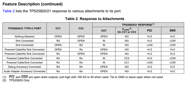
    For the TPS25820, you would need to either flip the CC pins for add an inverter to the POL pin:

    When CC 1 is pulled-down, POL sends a high signal.

    If this signal POL were sent to the TUSB1142, this would cause the TUSB1142 to flip the mux for TX/RX2, even though the data is meant to be sent over TX/RX1. Hence the requirement for flipping the CC pins or an inverter on the POL pin.

    The important part between a CC controller and the TUSB1142 is that when CC1 is pulled down, TX/RX1 should be the path on the TUSB1142, and vice-versa.

    Thanks,

    Ryan

  • Hi Ryan,

    yes I understand. What throws me off is the EVM implementation. 
    How can it work then?

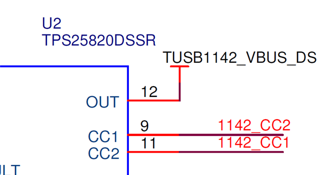
    The CC Pins are inverted:


    And there is an 'inverter':


    Which is a real inverter according to this post:
    https://e2e.ti.com/support/power-management-group/power-management/f/power-management-forum/1537811/tusb1142evm-why-are-cc1-and-cc2-flipped-on-the-schematic?tisearch=e2e-sitesearch&keymatch=TUSB1142%252520CC1

    However it says U8 is "do not include". Without U8 there is no connectivity to the Flip pin of the TUSB1142. 
    Which leads me to believe that a regular NMOS is placed in a inverting configuration. 

    "In the BoM we see that U8 and U9 are listed out to be n-channel MOSFET. They were designed with this intent, and JFETs were mistakenly used. U8 is DNI, U9 is populated, but the function is not often used.Any n-channel MOSFET with 3.3V compatible Vgs voltage will do. It is also possible ot route CC1 and CC2 in the normal orientation and remove the MOSFET inverter."

    I currently don't have the EVM and cannot check what is really populated. Do you maybe have access to one? 


    Is there maybe an updated version of the schematic?

    Kind regards
    Moritz

  • Hi Moritz,

    On the EVM, we currently have U8 removed, with a wire shorting pads 2 and 3 of U8 together to carry the signal to the TUSB1142. These are done as part of our assembly instructions to the fab, sorry for the confusion.

    This allows the POLZ pin to be sent to the FLIP pin while still inverted by flipping the CC pins.

    Thanks,

    Ryan

  • Hi Ryan, 

    thank you for sharing this information. This untangled the knot in my brain.

    Kind regards

    Moritz

  • Hi Moritz,

    No worries, sorry for making it a bit confusing haha.

    Thanks,

    Ryan