This thread has been locked.

If you have a related question, please click the "Ask a related question" button in the top right corner. The newly created question will be automatically linked to this question.

TPS61178: Over current waveform capture

Part Number: TPS61178

HI TI,

From the datasheet, I understand that the TPS611781 uses peak current detection for OCP. However, I couldn't find a corresponding waveform illustration. Could you provide a reference waveform (VOUT/SW/IL) when OCP is triggered? I want to ensure we are capturing the OCP behavior correctly. Thank you.
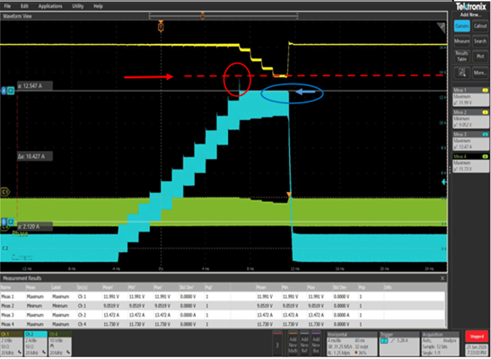
image.png


B/R, GAO


  • Hi GAO,

    I will have this test today, thank you for your patience.

    Best Regards,

    Fergus

  • Hi GAO,

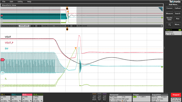
    Please see below waveforms at output short.

    The VOUT_P is the voltage before P-MOS.

    Best Regards,

    Fergus

  • HI Fergus,

    Regarding the red box, I noticed the SW duty cycle is shrinking. Is this because the IC has entered 'Pulse-by-Pulse' current limiting? Also, for a gradual current ramp-up test (instead of a short circuit), where should I place the cursors to accurately capture the OCP trigger point? Should I focus on the Peak of $I_L$ at the moment VOUT begins to drop? Thanks

    BR, GAO

  • Hi GAO,

    The duty is increasing with the output drops.

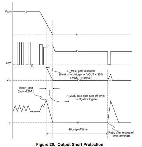
    Protection is triggered in two conditions:

    current reaches 20A and output drops to 30% of the normal value.

    You could choose either one as the cursor to capture the OCP point.

    Best Regards,

    Fergus

  • HI Fergus,

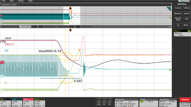
    I noticed the current marked at 30% output seems unreasonable and doesn't align with the R LIMIT setting. My LAB is seeing a significant discrepancy between the measured OCP and the RLIMIT theoretical value. I suspect we are not capturing the correct point. If we judge based on this 30% output point, the test will result in a FAIL. Or can you suggest how this test should be performed? Thanks

    B/R, GAO

  • Hi GAO, 

    The short protection current limit is normally 20A and is irrelevant with the RLIM setting.

    The protection is triggered either condition is met.

    In my test waveform, when the output decrease to 30% of normal value (about 5V with some variation), the P-MOS is shut down.

    I think it would be ok for you to trigger the 30% output point.

    I'm not clear what you mean by 'test result is FAIL'.

    In your waveform, it seems the device does not shut down because it does not stop switching.

    Is your OCP referring to a current limitation?

    It can be found that the peak current is limited to 12A, which could be some variation of Rlimit.

    Best Regards,

    Fergus

  • HI Fergus,

    Sorry for the misunderstanding. My goal is to confirm how to accurately measure the ILIMIT}$ threshold defined by RLIMIT. Our Lab is required to check if the hardware implementation matches the schematic. Therefore, I need to know how to correctly capture the Over Current trip point instead of a short-circuit event.

    BR/ GAO

  • Hi GAO,

    Thanks for explanation. 

    We slowly add load until the output voltage drops to 90% of the typical value to ensure the current limit is triggered.

    Then the measured peak current is just the ILIMIT.

    Your waveform is ok to do the ILMIT test. 

    The value is about 12.5A according to your waveform.

    It seems the value much higher than the set value, do you regard this as a Failure?

    The reason is that there is a slope compensation in the current comparator.

    This leads to current limit increasing when the duty decreases.

    Best Regards,

    Fergus

  • HI Fergus,

    Could you please help set I_{LIMIT to 14A (with VIN=5V / VOUT=11.3V) and provide a reference waveform for our target? We would like to use it as a guide for our measurements. Thank you

    B/R, GAO

  • Hi GAO,

    The device is not recommended to work with current limit larger than 10A, the device may face damage.

    I will set it to 10A and see if the value reaches 14A with your voltage condition if you want it.

    Best Regards,

    Fergus

  • HI Fergus

    I think this is a great suggestion. Let’s use 10A as the reference template. Thank you

    B/R,

    GAO

  • Hi GAO,

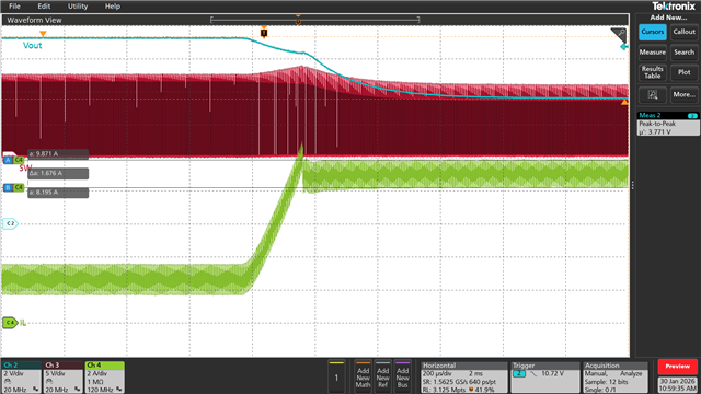
    I have set the Rlim with 75k.

    Please see my waveform of current limitation.


    The measured peak current is 9.87A. Unfortunately, the value is far away from 14A.

    I think you can measure the current limit similarly.

    Best Regards,

    Fergus

  • HI Fergus,

    Thank you for your support, I have clarified everything.

    B/R,

    GAO