This thread has been locked.

If you have a related question, please click the "Ask a related question" button in the top right corner. The newly created question will be automatically linked to this question.

REF200: Current multiplexer for REF200

Part Number: REF200

Hello Ti,

I need to know the possibility of using a current multiplexer circuit for REF200 constant current source.

I need to measure two (1K) resistive lader positions once at a time. The distance will be around 25 meters so I choose 400uA current. I need to use a single REF200 current source so I can switch between two resistive lader. Currently I am using a SPDT relay to switch the current. Is there any way I can use to do the same  electronically without using an electromechanical relay?

The supply voltage is 24V. Can I use any specific analog motiplexer or any simple MOSFET switch circuit without loosing the current accuracy?


Udhay

  • Hi Udhay,

    Thanks for your question!

    As long as you have enough voltage headroom, the current accuracy should not be compromised no matter what configuration you are looking to use since the REF200 will adjust the output voltage to maintain a constant current. Perhaps a simple MOSFET switch controlled by an MCU GPIO could work.

    Could you please let me know what this is being used for? At 25 meters distance, this sounds like this might be an RTD temperature sensor, and the resistance of the 25m cable would also need to be accounted for. With some more information, I could also provide some more specific advice.

    Best Regards,

    Andrew Li

  • Hi Andrew,

    Thank you for your response.

    We are planning to use the REF200 to monitor the tap position of a high-power transformer (100MW+) for an On-Load Tap Changer (OLTC) project. Typically, the control room is located far from the transformer, and it is necessary to know the transformer tap position before initiating a tap change for voltage regulation.

    Transformers may have different numbers of tap positions, typically ranging from 17 to 40. The arrangement is similar to a potential divider, with a bottom reference, a wiper, and a maximum tap (top). Three wires are brought out from the OLTC.

    Our requirement is to automatically identify the maximum tap and continuously monitor the wiper position. Additionally, we need to monitor the maximum tap periodically to verify the integrity of the wiring and connections. Therefore, we must switch the REF200 constant current source between the maximum tap and the wiper at defined intervals. Currently, this switching is implemented using a relay, but we would like to replace it with an electronic switch.

    The resistance step value is 1kΩ, so ultra-high accuracy is not critical. The REF200 provides two independent 100µA current sources, which could be assigned separately to the wiper and maximum tap. However, due to the harsh environment and long cable length, we prefer to operate at 400µA constant current for improved noise immunity. Previously, we used an op-amp-based constant current source, but the output was unstable due to high ambient noise. The REF200 performs well at 400µA, and we have not yet evaluated it at lower current levels.

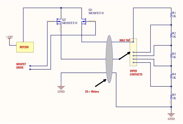
    As per your recommendation, I have attached the functional block diagram. Kindly review it and share your suggestions.

  • Hi Udhay,

    Thanks for the detailed explanation!

    Just to make sure we're on the same page, let me summarize my understanding:

    • There are two fixed resistances (R1 and R5 in this example which are the max tap and the reference resistance).
    • The number of wipers will change with respect to the transformer tap position.
    • The REF200 should switch between biasing the entire stack of resistors for max tap identification and biasing the divider starting at the current wiper contact.

    Is this correct?

    I don't see any issue with using a simple MOSFET electrical switch with this setup as long as the 24V provided to the REF200 is enough to provide the 400uA after going through the resistor ladder as well as the added resistance from the 25m cable after all wiper contact resistors are accounted for.

    Overall, I also don't see any issue with the block diagram that you showed. One thing to consider is to make sure that Q1 is completely turned off before Q2 turns on and vice versa. If both MOSFETS are on at the same time, this may cause some undefined or undesirable behavior.

    Best Regards,

    Andrew Li