This thread has been locked.

If you have a related question, please click the "Ask a related question" button in the top right corner. The newly created question will be automatically linked to this question.

LED Driver TLC5945 Clarification

Other Parts Discussed in Thread: TLC5945, TLC59711, TLC5971, AM3703

Hi,

I am planning to use TLC5945 for driving my LEDs (basically I have 36 LEDs - 12 each for Red, Blue and White).

I need a few clarifications regarding working of this chip

  • As per datasheet, max voltage at OUT terminal is 17V which means I can have three to four LEDs (based on forward voltage) in series at each channel. Now, each LED has a min to max rating for forward current which is 2.6V to 3.5V for my LED. If I connect 4 LEDs in series at each channel, I need to give ~15V (3.5*4V plus 1V headroom for OUT regulation).

Now, in worst scenario if all the LEDs have min value of forward voltage i.e. 2.6V, voltage at OUT pin will be 4.6V (15V minus 4*2.6V). As per fig 5 in datasheet, output current variation w.r.t. OUT pin voltage is shown upto 3V only. So, what will happen if voltage at OUT pin goes above 3V?

As per my understanding, power dissipation for internal switch will increase. But will it still be able to regulate the programmed current if I take care of heat dissipation? What is the max voltage limit at OUT pin such that device will be able to maintain constant current sinking upto a reasonable level of accuracy?

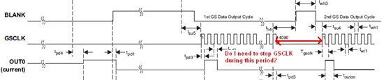
  • As per fig 6, after 4096 GSCLK cycles, this signal stops toggling and then BLANK goes HIGH. Does it mean that GSCLK should not toggle after 4096 CLK cycles and when BLANK is high? As GSCLK is given externally, such requirement seems unlikely but I just wanted to clarify.
One more thing, my requirement is 12-bit to 16-bit PWM resolution. Is there any such device which has internal oscillator for PWM?
Vini
  • Hello Vini,

    When the voltage on the OUTx pins will go higher than 3V, the current will still be regulated but the lower you keep the voltage on OUTx (but above the break of slope in Figure 5) the more accurate will be the current regulation. You just have to be careful with the power dissipation inside the IC.

    The power dissipation is: OUTx voltage * forward current per channel * number ofchannels that are on. When all channels have 4.6V and the channels have to sink 80mA and all channels are on, this translates into a power dissipation of: 4.6V * 80mA * 16 = 5.9W. With this scenario you need a cooling plate and a fan to get rid of the energy, I expect.

    What is the configuration of the LEDs you want to use? Do you have the same color LEDs in one string? Because then I expect that the forward voltage of the red strings is a lot smaller than for the blue or white strings. Then you might think of having a lower VLED for the red strings or add resistors in series to the red strings to dissipate the power.

    The IC is able to regulate the current up to the maximum voltage for OUTx, but this is just not recommended because of the power dissipation.

    The GSCLK stops after 4096 cycles to make sure that not another greyscale cycle is started. For displaying videos for example this is an essential feature because when BLANK is going high within the 4096 cycles of a GSCLK, the eye will recognize a brightness change.

    For 12 or 16 bit GS control and internal GSCLK, please check out TLC5970, TLC5971 and TLC59711.

    Best regards,
    Brigitte

  • Hi Brigitte,

    Thanks for your detailed reply.

    I am using Red, Blue and White LEDs and application is to stimulate eye for a medical device.

    I am attaching the block diagram showing LED connections. Worst case power dissipation is ~0.7W only in my case considering full range of LED forward voltage.

    5810.LED Logic.pdf

    Regarding GSCLK I need further clarification.

    1. As per my understanding, after 4096 GSCLK cycles, PWM stops and all the channels are OFF, even if BLANK is kept LOW continuously. And I need to give a small pulse on BLANK restart a PWM cycle. I will change PWM value every ~33ms and I am planning to use 20MHz for GSCLK and need not change PWM value every 4096 GSCLK cycles but still I will need to toggle BLANK signal. Am I correct? Or I do not need to give BLANK pulse until I do not want change PWM duty cycle in GS register?
    2. Now as I do not need to change PWM value every 4096 GSCLK cycles, should I stop GSCLK after 4096 GSCLK cycles and when BLANK pulse is given or can it be free running during this time? As shown in attached block diagram, I am planning to use 20MHz oscillator for GSCLK. I will use a timer in MCU to generate BLANK pulse every 4096 GSCLK cycles i.e. every 204.8us. The accuracy of this timer will affect generation of BLANK pulse but that is acceptable for my application. I am more concerned about the requirement of stopping GSCLK after 4096 cycles. Even if I use MCU to control the oscillator, there may be some additional cycles after 4096 GSCLKs based on timer accuracy. Is stopping GSCLK after 4096 cycles till BLANK is toggled necessary? What will happen if there are some extra clock cycles during the period shown below?
    Vini

  • Hello Vini,

    Let me try to clarify your GSCLK questions:

    1. As per my understanding, after 4096 GSCLK cycles, PWM stops and all the channels are OFF, even if BLANK is kept LOW continuously. And I need to give a small pulse on BLANK restart a PWM cycle. I will change PWM value every ~33ms and I am planning to use 20MHz for GSCLK and need not change PWM value every 4096 GSCLK cycles but still I will need to toggle BLANK signal. Am I correct? Or I do not need to give BLANK pulse until I do not want change PWM duty cycle in GS register?

      Answer: Yes, you are correct, after 4096 clocks, the outputs will automatically be turned off. This was wrong in my previous post. sorry. So you can use a fixed clock signal on GSCLK, but you have to toggle BLANK to restart a GS cycle.
    2. Now as I do not need to change PWM value every 4096 GSCLK cycles, should I stop GSCLK after 4096 GSCLK cycles and when BLANK pulse is given or can it be free running during this time? As shown in attached block diagram, I am planning to use 20MHz oscillator for GSCLK. I will use a timer in MCU to generate BLANK pulse every 4096 GSCLK cycles i.e. every 204.8us. The accuracy of this timer will affect generation of BLANK pulse but that is acceptable for my application. I am more concerned about the requirement of stopping GSCLK after 4096 cycles. Even if I use MCU to control the oscillator, there may be some additional cycles after 4096 GSCLKs based on timer accuracy. Is stopping GSCLK after 4096 cycles till BLANK is toggled necessary? What will happen if there are some extra clock cycles during the period shown below?

      Answer: You can leave GSCLK free running, but you need to toggle BLANK regularly.

    Sorry for the mixup in the last post. There are other parts from TI which generate a internal GSCLK or need an external GSCLK that will automatically restart, but the PWM resolution of these parts is smaller.

    Best regards,
    Brigitte

  • Hi Brigitte,

    One more clarification regarding TLC5945.

    In datasheet it is mentioned that thermal PAD should be soldered on PCB but it is not clear whether we can connect it to GND or VCC.

    Can we connect this PAD to GND palne? 

    Regards,

    Vini

  • Hello Vini,

    Please connect the thermal pad to GND.

    Best regards,
    Brigitte

  • Hi Brigitte,

    I am testing TLC5945 and I am facing a peculiar issue where TLC5945 misses some BLANK pulses and LED is not switching ON after that BLANK pulse. Two test cases that I did are explained below

    CASE 1: GSCLK is 26MHz and it is free running i.e. GSCLK does not stop at anytime. BLANK pulse is generated after more than 4096 GSCLK cycles and LED is ON for ~65% duty cycle and as you can see from below picture, LED switches OFF as expected but it does not switch ON after first BLANK pulse but switches ON after next BLANK pulse.

    CASE2: I was thinking that GSCLK timing w.r.t. BLANK can be an issue. So, I gated GSCLK such that GSCLK is OFF during BLANK pulse. Sequence is GSCLK OFF  -->  ~1us delay  -->  BLANK pulse for ~1us  -->  1us delay --> GSCLK ON. But even in this case, same issue persists.

    What can be the reason for this behaviour in TLC5945?

    Regards,

    Vini

  • Hello Vini,

    Is this repetitive and the output is just turned on once when you are sending 2 BLANK pulses? Show both cases above exact  the same behavior? Would it be possible to get zoomed in measurements of the above signals while working properly and while generating the problem? When doing these measurements, please observe at the same time GSCLK.

    Please check the XERR output in the above case. I wonder if the IC is maybe too hot to turn the outputs on.

    Are you measuring the signals with respect to the IC GND? Please observe the IC input voltage and the LED voltage to make sure that these stay stable during the measurements.

    Best regards,
    Brigitte


  • Hello Brigitte,

    This behaviour is not repetitive but random. Failure happens in both the cases above i.e. with continuous GSCLK as well as gated GSCLK.

    VCC and supply for LED are stable during failure condition. XERR goes Low when LED is switched ON but it becomes High again when LED is OFF or blank is high. This is expected as I have not connected LEDs at all output channels and XERR is going low showing LOD fault condition. Failure occurs with only one output channel ON @ 20mA and I think this should not cause TEF fault.

    I have captured waveforms for second case where GSCLK is gated. Below images should give more information. Images show

    1.  Failure condition 

    2. GSCLK and BLANK timing

    3. Zoomed image when LED switches ON normally.

    4. Zoomed image for failure condition when LED remains OFF after BLANK pulse

    Regards,

    Vini

  • Hello Vini,

    The measurements and timing looks good. What happens when you replace the IC with a new one? When the failure is also there with a new unit, could you send me the total application?

    Best regards,
    Brigitte

  • Hi Brigitte,

    I will test with new IC and update you.

    BTW, what do you mean by total application? Do you need schematics for LED driver?

    Regards,

    Vini

  • Hi Brigitte,

    I tested with 10MHz GSCLK and it is working without any issue. But issue is still there with 26MHz GSCLK.

    I have some doubts on the quality of 26MHz GSCLK as circuit is done on a bread board presently for evaluation.

    I will do some more tests with different GSCLK frequencies as well as with a better 26MHz GSCLK and update you.

    Regards,

    Vini

  • Hello Brigitte,

    I have some updates on TLC5945 testing with different GSCLK, though issue is still not resolved fully. I have tried many different clock sources and frequencies for GSCLK and results are summarized below

    1. With a clock from an MCU for GSCLK, I am not facing any issue (no BLANK pulse is missing). I tested with GSCLK from 13MHz to 28MHz.
    2. With a clock from an oscillator (26MHz), issue is still there. As there is no issue when GSCLK is driven by MCU, I was doubting my clock quality. But I have improved my setup and clock from oscillator is reasonably clean now and it is same as from MCU. But issue is still there. I have tried buffering this clock, using a schmitt buffer for improved rise/fall times and tried a different 20MHz oscilltor  and also used a gated clock during BLANK period for all configurations but issue is still there in all these configurations.
    3. I tried a different clock source from AM3703 (26MHz) but even in this case issue is there.
    Are there any specific requirements for GSCLK which are not given in datasheet?
    May be I am going in a wrong direction and issue is not with GSCLK.
    Are there any chances that BLANK  pulse is missed? As per my understanding it is an asynchronous signal and its timing w.r.t. GSCLK should not affect the operation.
    But after missing BLANK,  LED glows on next BLANK pulse and there are 4096 GSCLK cycles between two BLANK pulses and I do not think that all these clocks cycles  will be missed.
    Frankly, at this time, I am not sure how to proceed further but I will continue testing next week and try to resolve it.
    Any suggestions will be helpful definitely.
    Regards,
    Vini
  • Hello Vini,

    Normally the application should work without problems with any GSCLK. We did not observe any issues with an asynchronous clock up to now.

    1. Is the GSCLK from the same MCU as the BLANK signal?

    2. and 3. I do not have an explanation for this behavior.

    Would it be possible that you send the schematic and layout to the PIC (product information center) http://www-k.ext.ti.com/sc/technical-support/product-information-centers.htm?DCMP=TIHomeTracking&HQS=Other+OT+home_d_contact and refer to this post? I will then review both in detail and check if there is something that needs to be changed.

    Best regards,
    Brigitte

  • Hello Brigitte,

    Yes, GSCLK and BLANK are from same MCU when TLC5945 is working as expected.

    I have not done actual board for LED driver till now. I have mounted it on a test board and am using eval kit for MCU. There are lot of wires from one board to another and it will not be feasible to send this setup to you.

    In meantime, I have made some more progress on the issue.

    I used a single 26MHz for clocking both the LED driver and MCU and I am not able to recreate the issue with this setup. GSCLK is continuously running now and clock quality is also bit worse but still there is no failure.

    I also tried different frequencies for internal MCU timer which is being used for generating BLANK pulse to check whether it is a SYNC issue between GSCLK and BLANK but it is still working without any issue.

    So,  the issue is solved somehow but I am still not able to understand this behavior in TLC5945. In my final product, LED driver and MCU will be on separate boards and a cable will be running between the two boards. If same clock is needed for both MCU and LED driver, GSCLK has to be given over cable and I am not sure whether it will work or not.

    Regards,

    Vini