This thread has been locked.

If you have a related question, please click the "Ask a related question" button in the top right corner. The newly created question will be automatically linked to this question.

bq24725A - Adapter to battery transition and other questions

Other Parts Discussed in Thread: BQ24707A, BQ24725A

Hi Wang,

We talked about this the other day, but I think it's best if I post it on e2e so that others can follow the discussion. The customer basically wants to get a deeper understanding of how the part works in the following situations:

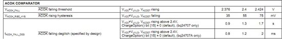
1. Adapter to battery transition: What is the mechanism by which this transition is triggered? I know the pin descriptions table in the d/s gives an outline (e.g. ACOK and ACDET), but can you provide a more detailed description? For example, if it's triggered by the ACDET pin going below 0.6V, then what is the hysteresis associated with it? I guess you get the picture of what kind of detail they are looking for.

6

ACDET

Adapter detection input. Program adapter valid input threshold by connecting a resistor divider from adapter input to ACDET pin to GND pin. When ACDET pin is above 0.6V and VCC is above UVLO, REGN LDO is present, ACOK comparator and IOUT are both active.


2. Adapter to battery transition: I understand the break-before-make time for this will depend on the system capacitance, and the BATFET will be turned on once the battery voltage is reached. To be more precise, is it the battery voltage minus the body diode drop of the FET? Also, once the battery voltage is reached, how much additional time is needed to turn on the BATFET? Internally, what causes this transition?

3. Power-on-reset: After POR, there is a default 150ms (typical) time before the device switches over to adapter power. But they won't have a battery available at startup, and would like to start up immediately from adapter power. Is there a way to work around this 150ms limitation from within the device or discretely?

4. Charge Inhibit: When the charger is turned off (by setting ChargeOption() bit[0]=1) and battery is disconnected, what happens to the SRN pin? Is it still pulled up to ChargeVoltage internally?

Ideally, is there any documentation that describes the above mechanisms in more detail?

Thanks in advance,

Mohammed

  • Thank you for trying help other people. I will answer those questions with following several posts.

  • First, it is better to have an EVM on hand if you want to know the detail waveform, timings...The EVM is alway tell you the trues.

    1. Adapter to battery transition (adapter voltage drop):

    a.  ACDET<2.4 or not: if ACDET is lower than 2.4, ACOK turn to low (ACOK is active, but, it is turned to low). The buck FETs stops switching. ACDRV is off. But, BATDRV is on when system cap is discharge to SRN voltage.

    See page 7 ACOK comparator for detail threshold and timing.

    b. ACDET<0.6 or VCC<UVLO:REGN LDO is gone, ACOK comparator and IOUT are both inactive.

    2. Adapter to battery transition (adapter voltage drop): What condition is BATFET on?

    See datasheet page 7th, ACN to SRN comparator. ACN to SRN falling threshold is talking about the BATDRV is turned on when ACN-SRN is around 200mV.

    3. The shortest /ACOK delay IC is bq24707A. It is 1.2ms. The customer always can do their own ACFETs and BATFET control circuit.

    4. bq24725A has very low BAT leakage current from SRN, SRP... pins. This is help reduce the quiescent current from battery. In another hand, you may see the SRN pin voltage is not zero when charger is turned off and battery is disconnected. Some of leakage current is coming from the charge pump schottky diode between PH pin and REGN pin.

    The datasheet's function block diagram is good way to understand the internal circuit. I don't think we share the detail internal circuit design with public. If you have specific questions and issues, you can ask application engineer team. They can help you.

    Thanks,

    Wang

  • Hey Wang,

    Thanks for replying.

    1) So when ACDET is lower than 2.4V, ACDRV going low, turning off the AC FETs. At that point, the output is held up by the output caps alone until ACN is only 120-280mV higher than SRN at which point the BATFET is charged up in some amount of time. How long does it take to turn that BATFET on starting at the instant that ACN-SRN is (typical) 200mV? Is all of that correct?

    2) As far as the POR 150ms delay in switching over to adaptor power, can you explain how that 1.2ms number comes about? I don't see it in the datasheet. I also don't see how that relates to the idea of defeating the mode during POR where the device powers up on the battery alone.

    3) Any idea on what that SRN pin could leak up to? Is it clamped? Is there a typical value?

    Finally, aren't you part of the apps engr team? Is there someone else we should be talking to? Are they on e2e?

    Thanks.

  • 1. bq24725A drives a N-channel BATFET. So, bq24725A integrated a internal charge pump circuit. The BATDRV charge pump only has 60uA driving capability. For example: if the total Cgs is 10nF, the BATFET gate charge time is around t=10nFx 6V/60uA=1ms

    But, we don't need worry about the system load power. Before the BATFET is fully turned on, if the system voltage is lower than BAT, the body diode of BATFET can give a current path to system load.

    2. See bq24707A datasheet page 2nd or 5th

    3.  The total Ibat leakage current is on page 7th which includes Isrn. I can not give you the internal SRN circuit.


    Yes. I am part of the apps team. After reading the datasheet carefully, please post your question on the e2e. So, even I am not available, other apps can help you.

    To increase your post visibility to the whole apps team, you can start a new post with your new question.

  • Hey Wang,

    This is actually the same issue Mohammed asked about. Did you want me to start a new thread?

    For 1) The concern here is that they're running 22A on the output. They don't want the diode the conduct for very long as it's not made for that kind of current for a long period of time. So it sounds like the maximum time it would take includes the discharge of the system bus voltage down to 280mV below ACN and then additional time for 60uA to charge up the gate capacitance. We can assume that the IC reacts very quickly in comparison to the charge time?

    2) Ok so that's on the bq24707A datasheet, but that still doesn't address how we can guarantee start up only on the AC input - not battery. Furthermore, I don't see how these specs allow them to control whether or not the part starts up on the battery. Can you explain that?

    3) Ok I think this works.

    And ya I have looked over the datasheet, but it is in no way clear to me what some of these characteristics are actually measuring. It's quite cryptic in my opinion.

    Thanks again for your help.

  • 1. The maximum BATFET body diode working time is from BATDRV startup (ACN to SRN COMPARATOR flipping: the system voltage dropped to 200mV higher than SRN) to BATFET fully turn-on.  On the EVM (a 10nF external Cgs on BATFET), it is about 1~2ms. If the 22A 2ms pulse is in MOSFET's SOA, it should be fine. I am wondering what system use 22A?

    2. The delay time is nothing to do with battery connecting to the system load. The body diode of BATFET is always there. 

    Yes. The charger's state machine is not easy. That is why it is better to have an EVM on hand.  

  • Wang,

    One more question: the battery to adaptor transition should take about 10us, right? Does that transition happen at ACDET = 2.4V or .57V via page 7 of the datasheet?

    Thanks.

  • It is ACDET=2.4V. See datasheet page 13 "ACDRV" and page 22 "system power selection".


  • hello,
    How coulde i check it is charging?