Part Number: UCC33420
I am looking at a low-noise application using the UCC33420. To reduce noise during a particularly noise-sensitive measurement duration I want to turn the regulators off. I have been noticing, what seems to be, switching coming from the UCC33420 after the enable signal has gone low.
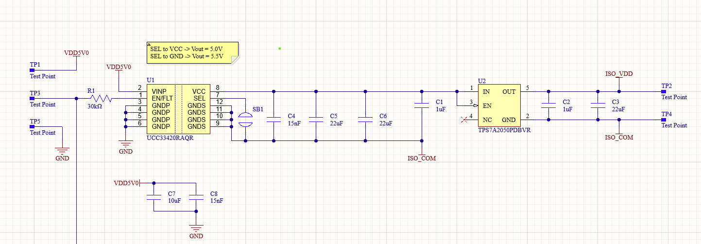
The schematic I was using is the image below. I have connected the solder bridge such that the input to the LDO is 5.5V.
Input voltage supplied from a benchtop power supply at 5V 3A.
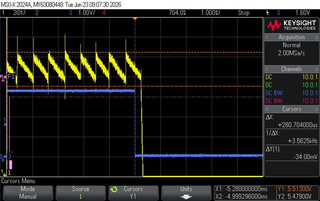
CH1 - probed directly across the output using a pogo pin for ground for short measurement loop
CH3 - enable signal, the enable signal is a 2Hz signal from a function generator with 80% duty (80% high)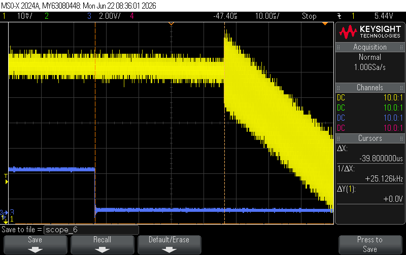
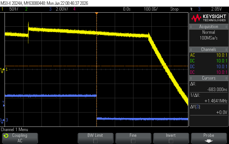
This switching occurs at different times after the enable signal goes low. This seems to be dependant on where the burst mode switching of the UCC33420 lines up with when the enable signal is pulled low. You can see this in the image below, the short increase in CH is the chip's burst mode switching.
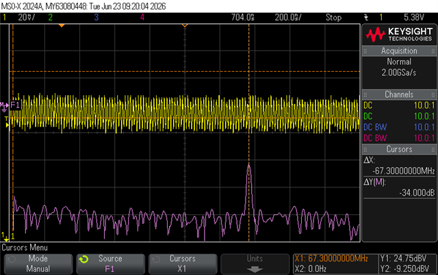
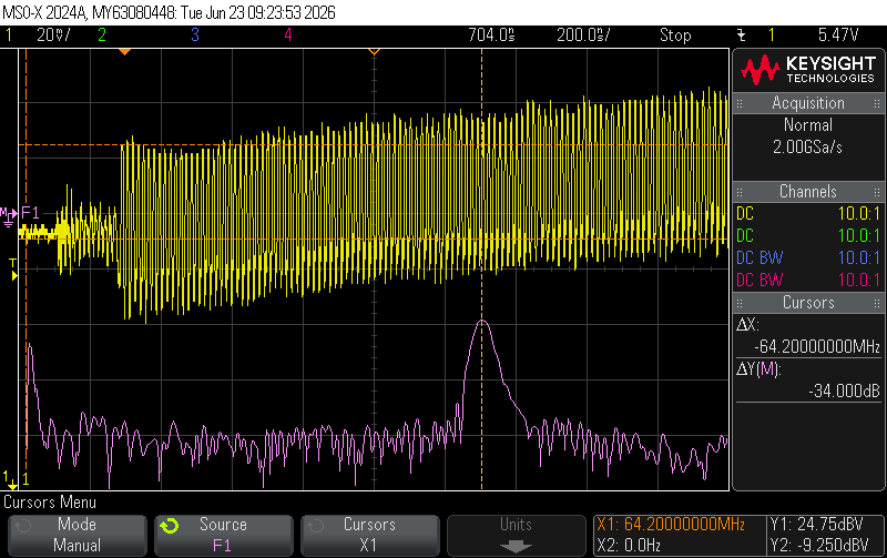
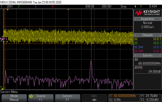
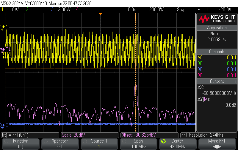
I removed the LDO and probed on the output of the regulator itself and measured the FFT of the normal switching and the switching during shutdown. The frequencies are not the same.
"Normal" switching:
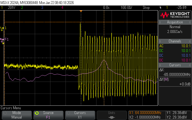
Shutdown switching:
Is there anything that I am doing wrong here? Is this expected behaviour of the chip? I have not replicated this exact measurement on this PCB with the UCC33420-Q1 but I have observed the same behaviour in a different design.
Any advice would be greatly appreciated.