Because of the holidays, TI E2E™ design support forum responses will be delayed from Dec. 25 through Jan. 2. Thank you for your patience.

This thread has been locked.

If you have a related question, please click the "Ask a related question" button in the top right corner. The newly created question will be automatically linked to this question.

gate driver needed for buck converter for wind turbine

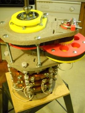
Greetings, I am working on a basic buck converter for a permanent magnet alternator that will be driven by a vertical axis wind turbine to charge a 12 volt battery bank. A discrete dump load controller will be used to divert the load when the battery bank is fully charged. The open circuit voltage of the permanent magnet alternator can range from 0 to over 200 volts. Max current output desired is 15 amps. This is a first attempt and I am requesting information on a suitable gate driver for a synchronous two fet buck converter. Any information will be greatly appreciated.

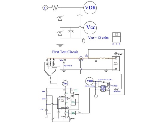
  • Hi, I managed to resolve most of the problems with the proto circuit when using the bench power supplies.  They were mainly caused from the power supplies and I had the new oscilloscope probes set to x10. 
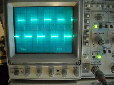
    I still have to resolve one problem. The output from the 555 oscillator has a severe ringing that is transferred to Vs of the mosfet.  But the boot strap appears to be working with the Vs from the IR2117 connected to Vs of the mosfet and the mosfet is turning on and off. 
    555 output
    Vs mosfet
  • The IR2117 seems to be a suitable gate driver for the application, so I would be more apt to suspect the oscillator circuit of causing your problem. If you have access to a signal generator, you might try using it to supply a cleaner waveform to you gate driver's logic input, and see if this resolves your issue.

    Also, many semiconductor companies offer integrated Buck controller circuits. Using one of these controllers could save you quite a headache, as they act as oscillators and also use voltage feedback from your Buck's output to alter the duty cycle of the waveform, ensuring a better-regulated output.

    If you need some good references about Buck design, the best one I have found was an old TI paper from about 10 years ago, titled "Under the Hood of Low-Voltage DC/DC Converters". Try googling it, because I'm having trouble linking directly to the PDF file.

    Also, here's an article about the various methods used to reduce the ringing at the source of the switching FET, while also explaining some of the causes: http://low-powerdesign.com/article_tamingthebuck_082510.htmlebuck_082510.html

    Hopefully this could be of some use to you. Good luck!

    -Alex

  • Hi, I managed to get the buck converter working with a resistive load. When I replace the resistive load with a 12 battery the mosfet starts to turn on then immediately turns off. I am not sure why?
    video of PMA using Buck converter driving a 50 watt 12 volt load:
    I noticed that different projects use different methods, some will use a gate driver with a bootstrap capacitor and others will use a gate driver that is powered with a isolated power supply. I am confused by this, are there any links that do a side by side comparison of the two methods?
      
  • Greetings, using a isolated power supply and FOD3180 does work. I am using a blocking diode between the inductor output and the plus terminal of the 12 volt battery. The gate driver is triggering a N channel IRF540 in a Buck circuit configuration and is charging the battery, current about 1 amp. Then I replaced the battery with the 50 watt halogen light and the circuit was able to illuminate the light after I adjusted the duty cycle, current max about 4 amps. I was manually operating the PMA. So far this is a very happy day. The next step is to drive the PMA with the drill press to determine how the circuit behaves at a higher RPM.     
    Chapter 4. page 69 
    http://etd.ohiolink.edu/view.cgi?acc_num=akron1320692738
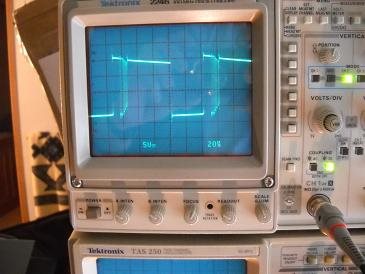
    Isolated power supply with FOD3180 gate driver. N channel Buck converter using a IRF540 mosfet. Bottom wave form is gate of mosfet, top wave form is source of mosfet.
    Input voltage max about 40 volts. Output current varies depending on duty cycle. Circuit still needs improvement but it is working. Input voltage is from a permanent magnet alternator and is being manually operated.   Comments welcome.