hi
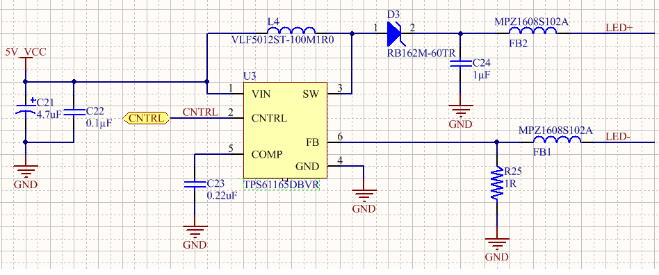
I got my first prototypes of the PCB based on the TI TPS61165 led driver. SOT-23 package - hand soldered
For some reason that are not clear to me now it's not working as expected do I want need some assistance.
Attached is the electrical scheme only R3 is connected and R4 is open ( used for future PWM control)
My LCD operates with 20mA current and 19VDC and when I plug it in the TPS61165 doesn't work. No switching is observed.
I checked of course that everything is connected where its suppose to and the power consumption is indeed 20mA everything was supposed to work but for some reason it doesn't.
when i feed the LCD from a lab power supply directly 19V i can see it works and consumes 20mA as expected.

Regards