This thread has been locked.

If you have a related question, please click the "Ask a related question" button in the top right corner. The newly created question will be automatically linked to this question.

BQ24070 not obeying it's charge current equations in mode=low

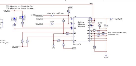
I hope the schematic comes through okay.  I have a 1800mAh Li-ion, 3.7V single cell battery.

I'm using a USB cable but we're going through a wall charger.  I've been using mode low.  Should I use mode high?  We don't have the pins available on the mcu to handle that pin so I need to tie it.

We are seeing strange current limiting.  I have Rset at 2.2K to get 482mA of recharge current, but it never seems to get anywhere near that and starts out around 220mA and then slowly drops. I've changed the Rset value to be 500ohms thinking I'd go for the gold and see if I could increase the current.  This all seems to be true for either wall power or pc usb port power.  Too low current.

Why is my current so low?

Also, stat LED's behave strangely when they get near the full charge threshold.  I've increased the Rtmr resistor so I can watch it for over 9 hours.  When the current drops to around 60mA, both LED's start flashing.

Any thoughts?  I've waited too long to seek support on this issue and now I"m in a critically important time and need help immediately.  Please let me know as soon as possible.

Thanks,

David Havell

  • I can't read your schematic values so it is hard to say what is happening.  Please attach a schematic that is clear.

    The best way to trouble shoot on this part is to look at the function block diagram.  It is pretty detailed and shows all of the control loops for the input controls (Q1) and battery charging control loops (Q2).

    Basically the two controls are independent and some what in series.  ISET1 programs the desired charge current, but the input current has to be available through Q1 and Q1 supplies current to OUT and BAT.  What does the input current measure and is part of it going to the OUT pin?

    Is the DPPM resistor less than or equal to 35.7k?

    The quickest way to get help is to use a 4 channel scope and capature each pin of the IC during the low current issue and then there will be a good input where the issue can be identified.  Customers say that when doing this they most often see the issue themselves.

  • Hi Charles, thank you so much for jumping right on this.  I'll keep it going and get you as much information as you need to help me resolve this issue.

    I'm not sure how to paste a better image.  I'll try attaching it.

    1033.BQ24070 schematic.pdf

    The schematic shows a 37K resistor on DPPM, but I've changed it to 35K.  The current board I have has mode tied low, not the option shown in the schematic.

    I will put the scope on IN, OUT, BAT, and DPPM?  Are these the pins you are talking about?

    I have done some more looking and the recharge current varies quite a bit among different boards which all have the same components.  I'm not sure how to explain that.  Do you have any ideas.

    Thanks again Charles,

    David

  • Charles,

    As I'm working on this I guess the biggest question I have really is this: should I be able to get near 500mA using a USB wall charger if I'm in mode=low?  (Provided the wall charger has enough current available.)

    Thanks,

    David

  • You need a 10uF ceramic capacitor on the IN and OUT pins.

    Probably can use a 35.7k on DPPM but not any larger.

    Also include the STAT pins, ISET1/2 and TS.

  • The data sheet has the information...400 to 500mA for USB mode ISET2=High, unless your source can't provide it.  The typical number is ~440mA.

  • Right.  I have ISET2=high but I only get around 200mA.  Obviously I've got something wrong and those 10uF caps are part of it.  I've populated with too small values, so I'm changing that as well.


    Huge thanks again for your continued support.

    David

  • The overall system works best if the charge current is set as follows: 

    Assume the input will only deliver 420mA in USB500 mode and subtract the nominal system load; what is left should be the charging level.  Set ISET1 appropriately.

    The part is designed to give priority to the system over charging during peak loads so one does not have to buy an adaptor to supply peak load current and full charing current.

    It is defeating the purpose of this IC if the nominal system load plus the charge current always have the part in DPPM mode; one might as well use a simple charger and tie the system and battery together.

  • Hi Charles,

    Right now I am not powering the device, just trying to recharge the batteries.  There is negligible load when the device is turned off, just running an msp430 to manage on/off switch, reset, etc.

    The usage model for the product doesn't usually include using the device and re-charging the batteries at the same time; although it does happen.  However, my biggest concern right now is simply recharging the battery properly.

    I have Rset at 2.2K which should give me 482mA.  I assume that if I can get 420mA from the input then a setting of 482mA will just pass that all onto recharging?

    Am I configuring it in such a way that DPPM mode is interfering with recharge?  (I have to admit; I've read the datasheet many times and still don't have a great handle on DPPM)

    THanks Charles,

    David

  • Hi Charles,

    I have a question about the charge profile and flow, shown on page 9 and 11 of the datasheet as Figure 2 and 4.   Can you give me an idea on the relative time for the Termination phase?  Is it typically a significant portion of the overall charge time?

    I'm seeing better behavior, but the current falls off (I think because my batteries are all mostly charged) just like the chart on page 9 shows.   I'm just no sure about how long each phase typically lasts.  I know it will always vary some, but is there a general rule that Current Regulation and Termination phases are typically about the same time, or 2 to 1?

    Thanks,

    David

  • The taper portion (CV) is a RC time constant and gets shorter the lower the impedance of your battery.  Typically the taper is a little longer than the CC phase but can be less if you have a low impedance battery.  Most charges at 0.7C take ~3 hours.

    If the part enters DPPM mode the TMR pin will stop regulating at 2.5V and will drop proportionally to the reduction in charge current, up to a factor of about 3 and then is clamped around 0.8V.  If your part stays in DPPM mode, maybe you should increase the ISET1 resistor.