


Hello Forum
In my design I power the OMAP-L138 from TPS65070, but from the Literature which number is SPRZ301G I know that DVDD18 Can Pull Up to 2.7V When Using Dual-Voltage IOs at 3.3V. and now I have meet this problem.
There are 3 method to solve this problem in SPRZ301G :1, add a bulk capacitance, 2, add a additional shunt regulator, 3, add a resistor. Now I have tried the first and the second method. But I find that it can’t work.
1/ from the datasheet of TPS65070 I know that the DVDD3318_x ramp time for 3.3V is 250us, so I connect DVDD18 a capacitance of 20uF to GND, and find It no use. I add the value of capacitance to 30uF, 40uF, 50uF, and also find that it can’t work. The value of DVDD18 is still 2.7V. so I want know why it can be this?
2/ I attempt to Use the chip of tlvh431 to control the voltage at DVDD18, but also it failed. The follow figure is my design. (the signal VCC_1V8D is power to DVDD18 in OMAP-L138)
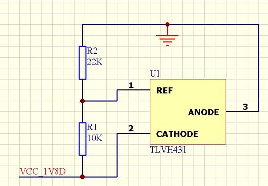
So am I connect right?
3/ I test in my circuit and find that the VCC_1V8D is 2.5V(It will be 2.7V if not use TLVH431), It seems that the chip TLVH431 didn’t work, but when I add a resistor between VCC_1V8D and TLVH431, as the figure below shows which is the basic circuit in the datasheet of TLVH431, I find that it can work, the VO is 1.8V.
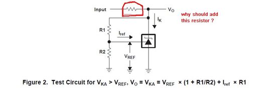
I was very confused to this. Because in my design, I can’t add a resistor in my 1.8V rail, it can consume power when it works. But it should work when the resistor is absent. So how to Use the TLVH431 to control the voltage at DVDD18? Could one give me a reference circuit?
4/ the figure below is come from the page 26 of SPRZ301G,
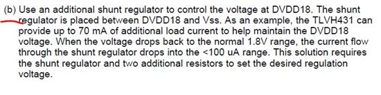
It says :”the TLVH431 canprovide up to 70 mA of additional load current to help maintain the DVDD18 voltage”. but the maximum leakage current will be 140mA, so how it can ensuring that the load on the DVDD18 supply during the DVDD13318_x supply ramp exceeds 140 mA? Use two TLVH431 chips? I have tried that, and find it also failed as above.
Your responses would be much appreciated!
Thanks,
xunliang
