This thread has been locked.

If you have a related question, please click the "Ask a related question" button in the top right corner. The newly created question will be automatically linked to this question.

PFC on a split rail DC output

Other Parts Discussed in Thread: UCC28019A, UCC28070

Hi everyone,

Im currently looking at providing PFC for a split rail +200/-200 power supply (maybe higher). Neutral is my common, and the +/- component of active(hot) is rectified to each of the required split rails. My output will not be isolated.

Can I use a single PFC controller in such an application? Or do I need two controllers - one for the positive component and one for the negative. I have noticed most controllers sit across the single rectified mains output - making their common negative going in relation to neutral and correcting only a single output (usually positive). 

 I may need to go as high as 3.6KW, so have been looking at the UCC28019A. Any suggestions on a topology for this problem? or controller? hopefully I have missed something.

Thanks,

Steve

  • Hi Steve,

    If you can tolerate the midpoint of your +/- 200V output be at 200V above neutral, a single pfc would work - output set to 400V - with a simple half-bridge active cap balancer to ensure that the two rails are symmetrical. If you need the midpoint at neutral, a variant of that active balancing circuit using a flying resonant capacitor can be used to create the -200V rail and keep the two rails balanced as well.

    At 3.6kW you might want to look at a continuous conduction interleaved controller to improve efficiency, and reduce input current ripple. A TI UCC28070 controller would work for this application.

    Regards,
    Brian

  • Hi Steve,

    Your design request is exactly what I am looking for, Great!!! I am going to implement such development into my audio amplifier design.

    Hi Brian,

    Thanks for your explaination and proposal!

    Do you have any doc or application notes which can be shared to us, concerning the >3KW PFC by using UCC28070?

    Thanks + Best Regards!

    Junpu

  • Hi Brian,

    This all sounds good. I wish to avoid an active clamped neutral and intend to make my neutral real (for compliance). My output will be -200VDC/0V (Neutral) /+200VDC Can you point me to a reference schematic regarding any of these topologies? Its a lot easier to absorb the concept of a "simple half-bridge active cap balancer" from a diagram for example.

    thanks,
    Steve


  • Hi Steve,

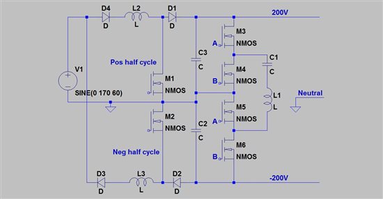
    The need for a 'real' neutral makes the topology for 120V a bit more difficult. It can be achieved by using two boost converter pfc stages - one for each half cycle. Unfortunately, the drive for the negative rail transistor is not referenced to neutral, like the positive rail switch is. I've attached a schematic showing Mosfet devices, but IGBTs can be used as well. The pfc stages are pretty self explanatory - each only runs for alternate half cycles of the line. That requires the rail balancer to even out the voltage ripple - which it will happily do.

    Operation of the rail balancer is quite simple. It behaves as a charge pump using C1 to shuttle charge between C2 and C3 depending upon which has the higher voltage. It is driven by a 50% duty cycle square wave. The two upper half bridge transistors get drive A and the lower transistors get drive B. A is on when B is off, and vice versa. Drive is most easily accomplished by using a transformer. L1 is small and has to be high Q, and C1 has to be a high performance film cap. C2 and C3 are bulk storage caps for the two rails.

    In the interest of topological clarity, things like EMI filters and snubbers are not shown. I've used the rail balancing circuit at up to 7kW for a high powered inverter. We had a single 400V dc input which the rail balancer split into +/- 400V using 4 TO-247 sized transistors and a 5uF film capacitor it operated at 50Khz. The inductor was about 1" diameter Sendust toroid.

    If you need to operate above 120VAC, a buck-boost stage can be substituted for the boost converters. It will also require floating drive to operate the switches.

    Best regards,

    Brian

  • I have never designed a split rail circuit.  However, when I look at your schematic if M2 turns on I think it will short C2 to ground through diode D2.

  • I discussed this with a colleague and I guess that is how a negative boost should work.

    Sorry

  • I think a Bidirectional switch  PFC with coupled boost  inductors would be the best candidate for split rail output with/without voltage balancer