This thread has been locked.

If you have a related question, please click the "Ask a related question" button in the top right corner. The newly created question will be automatically linked to this question.

What may be the problem with my LM5010 design?

Other Parts Discussed in Thread: LM5010, LM5008, LM5007, LM5010A

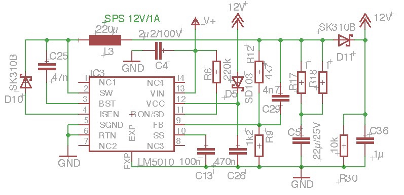
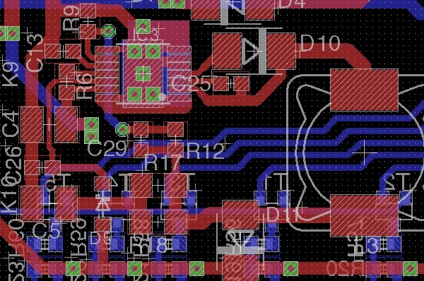
I've designed a DC/DC converter from 48V to 12V using LM5010.

The output gives just about 7V, which breakes down to about 3V when I connect an 1kΩ resistor.

I tested it with two chips (to see if one is defective) an tried to change some resistor values - no success.

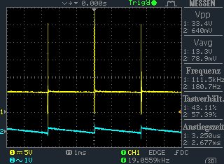
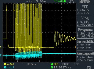
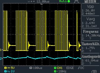
Voltage on FB-Pin never reaches 2.5V (<1.5V measured with oscilloscope). 

Similar designs with LM5007 and LM5008 are working without problems.

Please see the attached drawings...

  • Hi Thomas,

    I wonder if the part is switching at all.

    Can you probe the switch node to see if it is switching?


  • Also please check the following:

    • Probe VCC to see if it up.
    • Check if the VCC diode (D5) is flipped.
    • If possible remove D5 and check the circuit operation.


  • I checked D5. VCC is 7.05V and okay I think.

    Now oscilloscope pictures (input voltage = 25VDC):

    Ch1 = @cathode of D10 / left side of L3; Ch2 = AC part of Vout

    Pict. 1: open output, DC-level = 5.5V

    Pict. 2: Same as 1 but central pulse strechted

    Pict. 3: 100Ω connected @ output; DC-level down to 2.5V

  • Hi Thomas,

    I don't see anything wrong in the schematic. I would go back and check all the values and connections.


  • BTW, it is possible to remove C36 and all other capacitors downstream. I want to make sure that the converter is getting enough ripple.

  • BTW did you try removing D5?

  • Hi Thomas,

    Is it possible that because of some wrong connection the output is not connected? For example output capacitor not connected. Or R17/R18 are stuffed wrong so that there is no connection to the output capacitor or the load. May I request you to check that?

  • Meanwhile i desoldered R6 and replaced it with different values.

    Going >1MΩ suddenly 12V are appearing in a window of input voltages between 20 and 45V (depending on the value of R6, bigger for higher voltages).

    The Wave form on cathode of D10 changes to a nearly square (duty cycle about 40%) with f = 15kHz. I can have currents up to 1A at 12V.

    :(

    I even replaced L3 with an other type - no effect.

    If I add a "Rcl" between pin 4 (ISEN) and GND the frequency is reduced to about 5 kHz and Vout goes down to 1V.

    Removing D5 changes nothing, Vcc is 7V as before.

    Removing D11 the same: no effect.

  • I now have checked all solder connection of really every part. There ist no missing connection and no short.

    I don't know what to do anymore.

    The last hypothesis: both chips are defective (from the same series).

  • Well..can you check R17/18 connections.

    What is the voltage at RT pin?

    If all this does not give anything, I may have to accept your hypothesis. (Do you have a third IC?)

  • R17/18 are okay of course - all connections as they should be and the values are okay.

    RT pin? I can't find such a pin I'm sorry.

    Do you mean: FB pin? Or RTN?

    And I don't have a third IC (for I thougt that two ICs for one prototype should be enough ;-)

    Maybe I have to order some from a different distributor.


  • I meant RON/SD pin

  • Voltages vary with resistor values and input voltages.

    Voltages on Ron/SD @ Vin = 25V

    R6 = 220kΩ: 1.7V

    R6 = 1MΩ: 1.4V

    R6 = 4.7MΩ: 1.3V

  • Meanwhile...

    I'd ordered a new LM51010A.

    Result?

    Similar: no correct function..

    Because I soldered the LM5010A on a new board I took a 2A ultrafast non-schottkydiode as D10.

    I used the type MURS240 (2A/300V) instead of SK310B (3A/100V shottky).

    Because of of the non-shottky-diode I replaced the MURS240 with a shottky type I had lying around.

    It was MBRS100 (1..2A/100V shottky).

    Bingo!

    12V at the output and not influeced from input voltage in the range of 20…60V.

    Success. Partially.

    Testing the available current I was not able to get more than 400mA with stable 12V

    Trying higher loads decreases output voltage.

    Experimenting with different inductors and frequencies (values of R6) didn't help.

    After a little accident with the scope probe (connecting two pins) the IC died.

    This was enough trouble with this chip.

     I think I will replace the LM5010 with another chip from LT and make a new board. Its a pity, but there seems to be no shure way of getting 12/1A out of a LM5010 and I'm not willing to spend time in this any more.

    I can not understand that the diode is so critical.

    I can't understand this because LM5007 make no problems an delivers more than the specified 500mA stable (with BRS110 or SK110).