This thread has been locked.

If you have a related question, please click the "Ask a related question" button in the top right corner. The newly created question will be automatically linked to this question.

TPS61027 fixed 5V Boost Will Only Output 4.6V

Other Parts Discussed in Thread: TPS61027, TPS61200, TPS61253, TPS61240, TPS61070

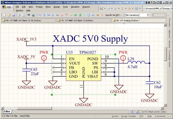
I am having a low output voltage issue with a TPS61027 we have designed into a new product, that is ready to go into production. Since this is a fixed voltage charge pump, there are no feedback resistors I can play with. I think all that is left is the inductor. The markings on the part seem to indicate the proper device. The inductor we are using is a 4.7uH NR3015T4R7M, and I am including a schematic below.

There is no load on the supply, it is attached to an external connector to supply a utility 5V for any potential external devices.

 I checked the output with an ohm meter and it shows >500K Ohms, both polarities.

 I note that there is mention of needing a minimum ESR, is this still true? Is there a recommended output cap that will fit, and make this work? Might I need a minimum load to make the device function properly?

The layout is very tight, with fat traces to everything.

This is very urgent for us as we are about to go into production. Your help is very Appreciated!

  • Each TPS61027 device is tested to ensure that it outputs 5V when used.  So, I have a high confidence that this is an application issue with your configuration.  Be glad that you tested this circuit before going to production.  Other customers are not that prudent.

    Yes, the device does require some ESR in the output capacitor for stability.  This is explained on page 17 of the datasheet.  A 2.2uF ceramic in parallel with a larger tantalum capacitor is the recommended configuration.  You need to replace with (ceramic?) capacitor with an appropriate one that meets the part's requirements.

    There is no minimum load required.

    We make an evaluation board that you can test your circuit on.  Then, you can just copy that layout into your design.  Layout is a critical step and needs ot be carefully followed.

    Your inductor only has a saturation current rating of 1A.  This is likely an issue with this part which has a 1.5A switch current limit.  You need to check, based on your output power, what current the inductor needs to handle.

    I would highly recommend looking into some of our newer boost converters which support ceramic output caps and offer performance improvements over these older devices.  Examples are TPS61200 and TPS61253/6/9.

  • Hi Chris,

    Thanks for taking the time to reply...

    This is a really hot project, and I am not seeing the simple fix here. I am not seeing a clear explanation of what the problem is either. That there is not anything wrong with the chip, is good news, but I need to verify the problem and a solution.

    Since there is no external FB for this part, it seems to me that the internal FB has some issue related to the external circuitry. Is there some way to boost the output voltage perhaps by changing the inductor value?

    I went back and read up on the ESR issue, my uderstanding is that this would affect output ripple, but not DC output voltage level, especially in a no-load condition. . Since I have no load, and the final application will a have a light load of 150mA max, this should not be a problem.

    Note that at 150mA max load, the inductor saturation value should not be an issue either.

    One thing I do note is that under the "TPS61027 Issue" post, 8-17-2009, susan has a similar issue of 4.6V (the same value I see) and no other responses... do you know what her issue resolution turned out to be?

    Thanks,

    Bill

  • Regarding that post, no that customer did not give us the insight into what was causing that issue.  But it sounded like they were starting the IC into a heavy load.  As Michael pointed out, this IC cannot start into full loads, but they can be applied after it has started.

    We need to make sure you are using the IC in a recommended configuration.  Then, we can evaluate the output voltage it gives.  You need to add some ESR to your output cap to bring it within the part's requirements.  I would replace your Cout with a 2.2uF ceramic in parallel with a tantalum cap with ~80 mOhm ESR.  You should also disconnect anything downstream of the IC to isolate it from other components.

    With only 150 mA load, I would highly recommend the smaller TPS61070 or TPS61240 over this IC.  You generally want to use an IC that can provide your maximum output current plus a little extra--not 5 or 6 times what you need.  In fault conditions, your board, traces, inductor, etc. are better suited to the lower current offered by smaller ICs.


  • If you could send us waveforms of Vbat, SW, and vout that would help up debug it from here.  We will build up your circuit on the EVM here and see what results we get.

    I don't believe simply changing the inductor will help.  But since you're operating outside of the recommended operating conditions with respect to the ESR in the output cap, it could.  The ESR is needed for the control loop to regulate.  It is surprising that it seems to be regulating to a different DC value but it is not designed to regulate properly without ESR.  Obtaining the time domain waveform of Vout will provide valuable information about the 4.6V that the multimeter is giving you.

    Something else you might try is tying the PS to ground to operate the IC in power save mode. 

  • Hi Chris,

    I took some pictures... hopefully this will help... let me know if you don't get them...

    The first is the sw pin, second the Vbat pin, third the Vout pin.

    I will try the PS pin next, then try replacing the ceramics.

    Thanks much,

    Bill

  • Thank you!  The pictures came through great.  You have a low frequency oscillation on the output which is symptomatic of control loop instability.  Also, your input is moving around quite a bit.  It's not clear if this is originating from the output voltage.

    Both those tests would be good to run.  You might also try adding a large input cap (100uF for example) to try and keep the input stabler.

  • Thanks to you!

    OK, I replaced C62, the 10uF mlcc input cap with a 100uF 6.3V mlcc in the same 0805 footprint used elsewhere. This cleaned up the input considerably, but also reduced the DC output voltage to 4.3V.

    So I looked around and found an old Tantalum TAJB226M020RNJ 22uF 1.8ESR 1210 and stuffed this into the Ouput cap 0805 footprint... and it worked! 5.01VDC, low ripple!

    So we are almost done... I see I can get a TLJR226M010R3800 22uF 3.0ESR 0805 10V. Do you think the 3.0ESR will be OK?

    Thanks,

    Bill

  • Great debugging!

    We also ran some tests and found that with a 10uF ceramic Cout the output voltage was indeed lower--around 4.5V.  So, possibly your 22uF simply suffered from excessive DC bias loss of capacitance (not surprising at 5.5Vout) and reduced the effective Cout to around the 10uF that we had.  So, the combination of low Cout and no ESR caused your issue.

    That tantalum cap with 3 Ohm ESR does meet the requirements for stability.  But 3 Ohm will give a lot of ripple voltage.  So, I would recommend using something more along the lines of the typical circuits in the datasheet--47 or 100uF with 100-300 mOhm ESR.  This would give optimized performance.  Also, I would highly recommend that a small 0402 ceramic 2.2uF be placed on the output to help the IC snub the rectifying switch.  A small low ESR ceramic is desired for this purpose since it has low impedance.  Ideal output cap configuration then is 2.2uF ceramic + 47 uF tantalum both placed as close to the Vout and PGND pins as possible.