


We have designed an inverting buck-boost converter (+6.5V in to -25.5V output - 250mA) based around an LM5085 buck converter.
LM5085 design:
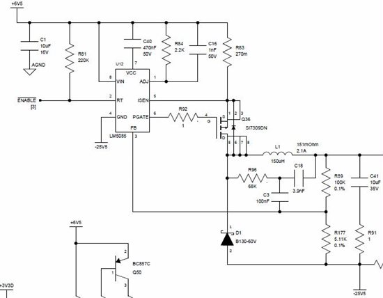
In testing this design all is working fine up to around 25mA after which the voltage regulation is lost.
(reference voltage cannot be maintained to internal 1.25V voltage - no issues with current peak limits and sufficient ripple voltage is present on feedback regulation pin).
Based upon application notes and provided reference designs for such a converter using Webench as reference use of an input to output capacitance was added (prototype) with some improvement performance (out-of-sync now at around 50mA load). Note that no 'ideal' capacitor was available to optimize the circuit)
Specific component (capacitor value and low ESR) selection and proper installation is likely to improve performance, but unsure whether this will be sufficient for full range current operation.
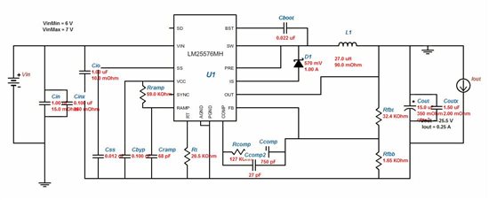
However, prior to enter this detailed optimization mode, we are wondering why the LM5085 is not listed in the solutions list for the inverting buck-boost topology.
Given that principle circuits are both more or less equal, can you advise if LM5085 can be used in inverting buck-boost topology and, if not, what the reasoning for not recommending this part?

In case the LM5085 can be used, can any further advise be given on the specification for input and output feedback capacitance (between Uin and Uout) and/or other means to ensure stable operation over full load current range?

Thanks in advance for your feedback

Best regards
SKF Condition Monitoring

Ludo Gommers


