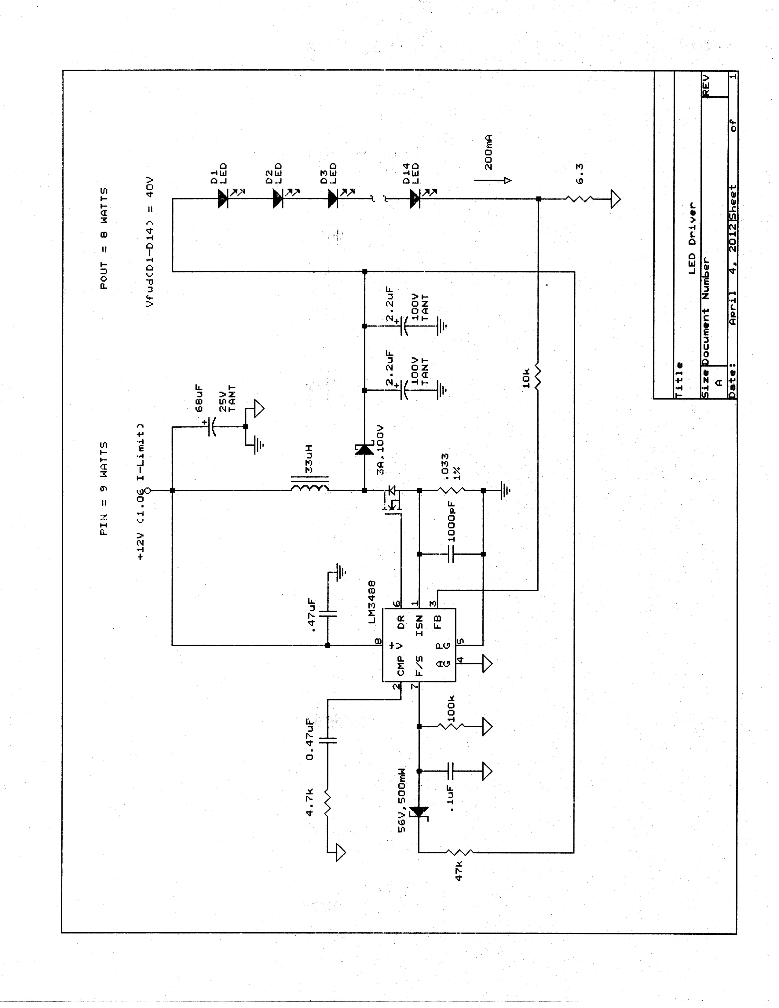
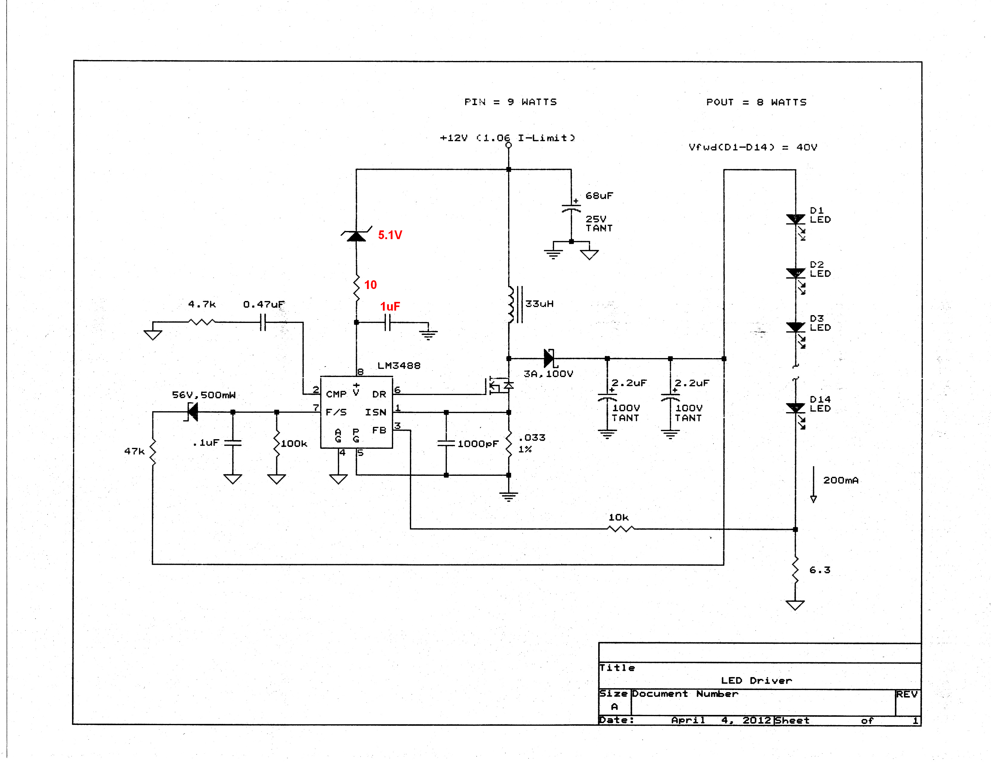
I have the LM3488 designed in many of our standard products configured as a simple boost converter. One in particular, is our series of lower power (<10watts) LED drivers. I have the LED return current flowing thru a sense resistor that develops the feedback voltage on pin 3. I like this current-mode controller due to its size and cost. It has worked flawlessly with over 10,000 of our products fielded. The other day a customer called complaining of an issue that hinged around the fact that he was powering our driver with a limited current source power supply. What appears to happen is at Time=0, his power supply smoothly ramps up to +12V as seen on pin 8 of the controller as well a one side of the boost inductor, you can see the drive output, pin 6 become active (Fswitch = 150khz). In about 5ms the output reaches it nominal output current of 200mA thru a load that drops 40V (8watts). No issues and input current to booster = .75amps @ 12V or 9watts input, yielding an efficiency of 88.9%, all is well.
I mentioned the customer’s power supply has current limiting and its set to 1.06A. What happens every so often on power up is as the input voltage comes up, it triggers the over current function. Upon close inspection it happens at 8.5V or lower, which is what you might expect as the input current to supply 9 watts in is over 1.06A. Now the not so good part, when the current limit kicks in on the user power supply, the output voltage folds back to around 5V. The whole system hangs drawing 1 amp. Closer inspection reveals the switching action to the boost mosfet stops. Looking at pin 6, the drive pin for the gate, it sits at around 4 volts forever!...no switching action, nothing but leaving the boost fet on and hence current flowing continuously thru the boost inductor. I would expect the circuit to act erratic because we are "starving it" during power-up, but shouldn't the drive pin still switch, regardless if the feedback pin (3) or the coil current sense pin (1) is not above their thresholds? - I'm thinking this is a state that is not appropriate for any switching control chip, because now the coil never see's any off time. Going around all the pins of the chip, I do not see any levels that are in appropriate to cause this type of behavior. As you know the part is designed to operate down to +3V and in this case it is still running at around +4 to +5V.
Any thoughts or insights would be greatly appreciated. Thanks in advance