Captured to TPS61253 - operation for Vin > Vout wiki page

This thread has been locked.

If you have a related question, please click the "Ask a related question" button in the top right corner. The newly created question will be automatically linked to this question.

TPS61253 - operation for Vin > Vout

Other Parts Discussed in Thread: TPS61253

Hi TIer

TPS61253 has input voltage range of 2.3 to 5.5V.

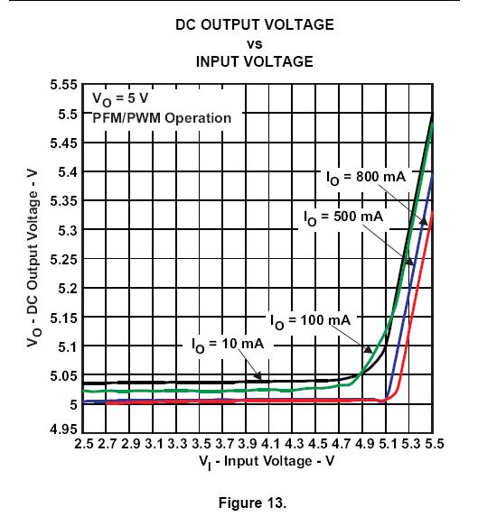
So, when Vin is above 4.5V. Is there any operating mode? things like 'pass through mode' or something?

Also when Vout(5V) is less than Vin(5V ~ 5.5V), Output is disable or Vin level?

1. Could you explain operation of TPS61253 when this device Vin level is form 4.5V to 5.5V?

2. And when Vin is 4.5V to 5.5V, is it OK for IC's safety?

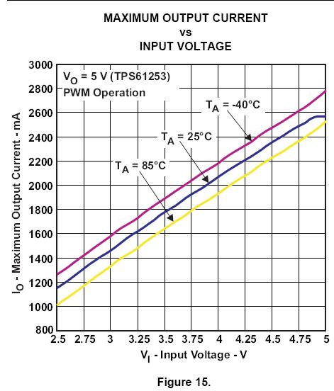
3. And when Vin is 4.5V to 5.5V, is it OK the output current is 1A continously?


Best regards

  • Jin, I hope you are finding the forum very helpful.  I would like to ask that you put more information in your forum subject lines. This will help others in the future if they have a similar question.  One example would be to use “TPS61253 - operation for Vin > Vout”  as the subject rather than just “Question about the TPS61253”.   Always begin the post with the part number.  More detailed subject lines are very important to help others know what the forum post is about.

    This question is answered in the datasheet, page 17.  This section describes that the IC can enter 0 duty cycle mode and not boost the input voltage if the output gets too high.  It then refers you to figure 13 that shows as Vin rises above Vout, Vout rises with it.  Essentially this is pass through operation.  The IC does not shutdown, it simply stops switching and does not boost the output further above the setpoint.  This is safe for the IC and it can supply the rated current so long as there is thermal fault due to excessive losses in the IC and assuming EN = 1.

  • Hi Chris

    Thank you for your quick response

    So, I think that you mean The IC can flow 1A at Vin> Vout.But, It may cause thermal fault due to excessive loss by RDS(on) of internal P-ch FET?

    we are only using 1A continuously. but IC can provide above 1A at 4.5V < Vin < 5.5V in the Datasheet.

    I think that you mean even if excessive loss can caused at Iout is 1A continuously.

    Is it right? If there is something to do to prevent thermal fault. Please let me know.

    Thanks

  • If your thermal layout of the IC is done well and your ambient temperature is low enough, you will not have a thermal fault. 

  • Hi, Chris.

    2 questions below

    1. If I made up my board with applying recommended condition in the datasheet, then is it OK 1A continously?

    2. TPS61253 Evaluation Board can generate 1A continously without thermal fault?

       Or need to other action for 1A continously?

    Would you tell me about it?

  • Ok.
    Finally I want to know that is it OK 1A continuously at 4.5V<Vin<5.5V without thermal fault
    When I designed with recommended condition in the datasheet?
    And is it OK 1A continuously at 4.5V<Vin<5.5V without thermal fault in the Evaluation board?
    In the datasheet, It seem to be OK. But it’s not plotted. 


  • Jin,

    Note that your posts resulted in numerous duplicates being posted to this thread.  Please be careful when posting in the future to only click 'post' once.

    Yes, the part can support 1A current as shown by the efficiency figures in the datasheet and figure 15.  A thermal fault is only a concern if you do a poor layout.  By copying the layout of the EVM, which s also shown in the datasheet, you can avoid this from happening.

  • Thank you Chris...

    There are some problem to register the question.

    Anyway I will do according to your recommendation.


  • Hi Chris,

    Please let me ask about output current capability at zero duty cycle operation. I'm not sure why Fig.11 show graph of Io=500mA and 800mA though there is following description in page 14.

    • Therefore the output can be kept as close as possible to its regulation limits even though the converter is subject to an input voltage that tends to be excessive. In this operation mode, the output current capability of the regulator is limited to ca. 150mA.

    Can you explain the meaning of 150mA in this description?

    Best Regards,

    Sonoki / Japan Disty

  • Hi Sonoki,

    Let me answer your question, 150mA means standby mode current , not Boost operation current.Please check the table 3 in datasheet in detail:

  • Hi Chen,
    Thank you for your response. Let me ask one more question.

    I believe that the output current draw from only PMOS at zero duty operation, then the maximum load current will be 1.8A at zero duty operation? I know that the junction temp should be care.

    Best Regards,
    Sonoki
  • Where did you get 1.8A?could you please post the screen shot where you get it?

  • Hi Chen,

    I referred abs max of Continuous average current into SW. Please let me know the correct value if I do not refer correct information.

    Best Regards,
    Sonoki

  • Yes, in this condition, Vin=Vo. Iomax ≈ 1.8A

  • Hi Chen,

    Thank you for your response. I can't verify this post because I'm not owner of this post, but please let me close this discussion.

    Best Regards,
    Sonoki
  • It's OK. And You can startup a new post if you have some other questiones :)