This thread has been locked.

If you have a related question, please click the "Ask a related question" button in the top right corner. The newly created question will be automatically linked to this question.

LM27313 will not start/switch

Other Parts Discussed in Thread: LM27313, LM2731

Hello

I've been trying to get the LM27313 to work in my application without any positive result. The circuit is done as suggested in datasheet, 5Vin to 12Vout, with slightly different resistor values for the feedback. However when applying a nice low ripple 5V the IC seems never to start switching the voltage as the output is 5V - ~0.3V = 4.7/4.8V. On the SW-pin I see no action at all, it's voltage is exactly the same as Vin without any measureable switching. The FB-pin is as low as 0.5V where it, according to datasheet, should be around 1.23V.

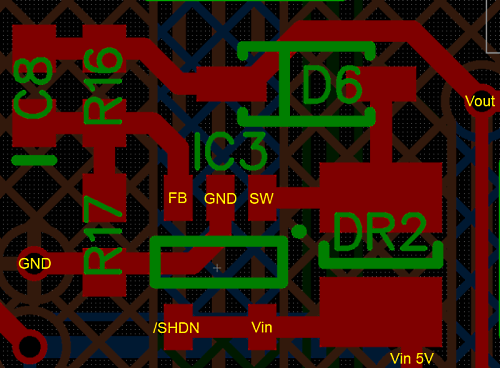
So in order to rule out any problem with faulty/destroyed IC, wrong voltage divider for feedback or anything else I made a new application circuit exactly as described in datasheet, new fresh LM27313 and with the recommended components. However this made no difference as all the voltage levels are the same as when measured on board my main application pcb. As far as I can see with my scope is that the IC never starts switching and stepping up the Vout for some, to me unkown, reason. Power supply in both cases were a stable low ripple 5V/3A.

Any ideas on what can be wrong?

  • Hello Andreas,

    it may be a layout issue, could you provide your layout?

    You can also try to mount the LM27313 on a LM2731/3 EVAL BOARD since they are pin to pin compatible.

    Regards,

    Giuseppe

  • Hello Andreas,

    Can you send us your schematic for review.

    Thanks,

    Allan

  • Due to certain restrictions Im only allowed to attach the part of layout where the LM27313 is used. One thing that comes into my mind is if the GND-pin has too long trace to the actual GND plane but still the total length of that particular trace is 5,36mm.

    Below are the component values of which I used on my main application pcb.

    Vin = Powersupply 5V/3A

    R16 = 150k 1%

    R17 = 18k 1%

    C8 = 220pF X5R

    D6 = 40V/1A schottky (SKL14 from diotec.com)

    DR2 = 10uH/1,1A

    Cvin = 10uF/35V X7R (out of picture but is 1,4mm from the yellow text 'Vin 5V')

    Cvout = 10uF/35V X7R (out of picture but is 0,8mm from the yellow text 'Vout')

  • Andreas,

    Thank you for sending the layout. I don't see anything that would cause such a severe problem.

    I can only guess that the part must be damaged in some way at power up. It is possible that there is overshoot on Vin.

    Can you monitor the VIN and SW voltages at startup and send me a scope capture?

    Thanks and regards,

    Allan

  • Thanks for the reply Allan

    I attached two scope pictures, one of my 5V with probe at LM27313 Vin-pin and one of the SW-pin of the IC.

    As you will see there is absolutely no action at all on the SW-pin and I turned my application on and off alot of times to see if I could get any type of overshoot without luck. However the 5V ripple wasnt as low as I thought, top-bottom at 47mV but cant really see that as a source of suspicious behaviour.

    Below is 5V input.

    <a href="http://tinypic.com?ref=2vx3mok" target="_blank"><img src="http://i43.tinypic.com/2vx3mok.png" border="0" alt="Image and video hosting by TinyPic"></a>

    Here is SW-pin at the LM27313

    <a href="http://tinypic.com?ref=k2yf41" target="_blank"><img src="http://i41.tinypic.com/k2yf41.png" border="0" alt="Image and video hosting by TinyPic"></a>

  • Added info as follows:

    Pictures below shows the action on Vin-pin and SW-pin when the external PS (powersupply) has been on for >5 seconds but where my application is powered on by connecting the cable from PS output to my application Power Input. My On/Off switch in this case is by putting power cable in the socket instead of turning PS on and off.

    In the pictures one can see a small overshoot when powering on and off by cable but nothing that I believe could harm the IC.

    <a href="http://tinypic.com?ref=e5jqbl" target="_blank"><img src="http://i43.tinypic.com/e5jqbl.png" border="0" alt="Image and video hosting by TinyPic"></a>

    <a href="http://tinypic.com?ref=34snv2u" target="_blank"><img src="http://i39.tinypic.com/34snv2u.png" border="0" alt="Image and video hosting by TinyPic"></a>

  • Today I've also measured the current drawn by the LM27313 in two different scenarios with a Agilent U1241B multimeter with range from 0.1uA to 10mA with 3 counts LSD accuracy. First measurement was done on my main application PCB and revealed that the IC only draws 134uA with SHDN-pin tied to Vin, On-state. For proper operation this should be around 2-3mA according to datasheet.

    Second measurement was done on a circuit equal to the eval-pcb layout found in the datasheet. The current drawn was sligthly lesser, approx 74uA.

    Measured four different IC's with same result regarding both current drawn and voltage on FB and SW-pins. As I'm starting to run out of options I ordered some LM2731X to try and see if they work in my application. As I understand from the datasheet it should be pin compatible and hopefully that will bring some clarity as my head is currently running in circles :)

    Edit: Ok, after getting a bag of LM2731X I simply replaced the LM27313X on my application PCB without any modifications, same resistors and capacitors which resulted in great success. The circuit now works as intended with proper switching and correct Vout at 11.47V with given voltage divider. Ripple at Vout is well below 40mV pk-pk. So, the only conclusion I can make of this is that either I missed some special parameter regarding the LM27313X or that they were simply faulty/broken.

  • Hello Andreas,

    the LM27313Q should work with no problem like the LM2731. There is no reason that new parts should not work. Could you please  send us one of the bad units for analysis?


    Thank you,

    Giuseppe

  • Hello Giuseppe

    Of course, I have 1 untouched and 4 that has been soldered on PCB and then removed but I'll send them all.

    Can you please email me the correct street address for the letter and who to set as attention?

  • Hello Andreas,

    the address is

    2900 Semiconductor Dr

    Santa Clara, CA 95051

    please ship it to Giuseppe Pinto.


    Thank you,

    Giuseppe

  • Hello, I have the same problem described in this post with the LM27313. It does not start switching and I see a short from the input. I've read the datasheet many times and replaced the part with no luck.

    The circuit is exactly as described in the datasheet.

    Here is some data:

    Vin: 12V
    Vout should be 24V
    L1: 10uH
    C1: 2.2uF
    D1: MBR0520
    R1: 249k
    R2: 13.3k
    CF: 82pF
    C2: 4.7uF
    SHDN! shorted with Vin

    Any suggestion?
  • Please send us your schematic and layout information. Where is the short from Input to? The absolute max on the Vin pin is 14.5V and your operating input is 12V. This is quite close and therefore you'd require to make sure there were no spurious voltage spikes causing damage.

    Regards,
    Akshay

  • Thanks for your fast response.

    Here are the layout and schematic:

    imgur.com/XdcwVBy,sZ58sUf
    imgur.com/XdcwVBy,sZ58sUf

    I also have a LC filter at the input formed by a ferrite bead and two large capacitors.
  • Have you scoped the input voltage waveform? Does it look clean or are there some spikes on it. The layout is not bad, but it would be helpful to layout as suggested in the datasheet page 17. The output cap ground and the Ground pin of the IC should be very close to each other and on the same plane. I would suggest removing all the relief connects. Even though the input current in the boost is not choppy, it helps to have the ground of the input cap to be as close as possible to the ground pin. Have you tried a lower input voltage to see what happens?