This thread has been locked.

If you have a related question, please click the "Ask a related question" button in the top right corner. The newly created question will be automatically linked to this question.

TLV70450 Maximum Current

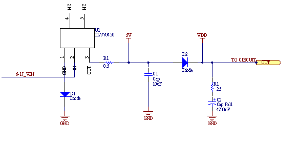
We are considering using TLV70450 in a battery operated device.  There is a 4700uF storage capacitor located at the output of the regulator (connected Vout to GND); we have measured the current draw of the capacitor by applying a 200ms burst when the capacitor is fully discharged.  We measured the instantaneous peak current to be about 500mA; the current immediately begins to fall as the capacitor starts charging.

Looking at the datasheet, the device is rated as a 150mA part; however, on pg.3 Icl (output current limit) is defined to be up to 1A at 0V (cap fully discharged).  Would the TLV70450 be potentially damaged by using it in such a setup or are we ok since we draw below 1A?   How long can TLV70450 operate at Icl?--what is the main difference between Icl and the rated current (150mA)? 

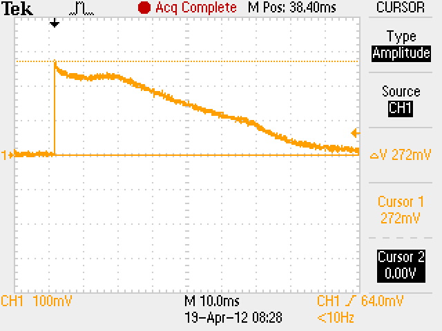
I have attached the current draw waveform-- we measured the voltage drop across a 0.5 Ohm resistor, so a 272mV peak voltage drop would correspond to 540mA.

Thanks,
Alex

  • Hi Alex, the current limit feature is meant to protect the IC during fault conditions. The device was not characterized outside its current rating so the specified charaterstics in the datasheet may or may not hold outside the recommended range. What will damage the IC though, as the datasheet suggests, is if it stays at current limit long enough to exceed the maximum junction temperature. 

    Regards,

    Darwin

  • How would we be able to calculate the maximum junction temp of the device?

    Could the TLV70450 to be used to charge a 4700uF cap?-- we could put a resistor before the cap to limit the current but the power needed to charge the cap would still be the same-- what is the power limit for this device-- how could we calculate it?  Does TI have other recommendations for safely charging large capacitors?
    Thanks

    Alex

  • Hi Alex,

    The maximum power dissipation can be caluclated on page 7 of the datasheet using equation 1 and 2. RthetaJA highly depends on the board layout and how much heat can be sinked. This value is on page 2 of the datasheet as thetaJA and is based on the JEDEC high board standard (see the foot note below this). As long as you do not exceed the maximum power dissipation rating using a 500mA current, the device will be okay. 

    If this does exceed the maximum power dissipation, then you can reduce this inrush current. These two papers explains these.

    http://www.ti.com/general/docs/lit/getliterature.tsp?baseLiteratureNumber=slva156&track=no

    www.ti.com/lit/an/slyt332/slyt332.pdf

     
  • David,

    Based on the 2 equations, it does appear that we could be a bit over the limit during the initial period (about 70us) when the capacitor begins to charge.  The period is very short and afterwards, the current consumption drops significantly as the capacitor charged.  For the testing, we are applying a 200ms pulse every 25s (the capacitor discharges during the remaining 24.8s over a 1K resistor).  Since the "high" current & power consumption periods occur very briefly, the total energy consumption of the device does not appear to be high.  However, is there a graph/description of the Safe Operating Area for this part (including the amount of time the device can operate at the various given limits).  I could not find this graph in the datasheet. 

    Thanks,
    Alex 

  • Hi Alex,

    Typically you would not see an SOA graph for our LDO datasheets. Indirectly, the SOA would be the operating conditions that would not exceed the abs max ratings on the datasheet. With that said, since you are slightly over max junction temperature, I recommend simply adding more copper to your layout (to dissipate more heat thereby improving your RthetaJA). Please use our EVM as a template.

    Regards, 

    Darwin

  • Hi Darwin,

    We are considering adding a 25 Ohm resistor in series with the capacitor in order to limit the inrush current to about 200mA and thus operate inside the power dissapation limits.  Would doing so potentially affect the stability of the regulator?  Will we need an additional output cap/etc to ensure stability?

    Thanks,
    Alex

  • Hi Alex, the LDO requires a cap at the output for stability. If you can increase the input voltage (enough for the resistor voltage drop and above dropout), you can put the resistor at the input side of the LDO.

    If you want to put the 25 ohms at the output, you can trying first putting a 1uF directly at the output, then the 25 ohms and 4700uF cap to limit the inrush.

    Regards,

    Darwin