This thread has been locked.

If you have a related question, please click the "Ask a related question" button in the top right corner. The newly created question will be automatically linked to this question.

Creating golden pack, power on power FET's to charge discharge cycle

Other Parts Discussed in Thread: BQ29330, BQ20Z40-R1, EV2400

I am using the BQ20Z40-R1 and the BQ29330 chipset to gas guage, and monitor a Li Ion pack.

We are using a pcb (evaluation board) with ckt very similar to the on page 15 of the bq20z40-r1 datasheet,  slus993A.

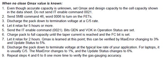
I am trying to create the golden pack, and am in the charge, discharge cycle.

My question is on the procedure for the discharge/charge cycle.

Our procedure as stands, is to apply a voltage across pack + and pack-, greater than the voltage to charge, and to simply use a power resistor to discharge the pack, from of course the same two pins.

When we apply the voltage, or the resistor across those two pins though, the batteries do not appear to be electrically connected, they neither charge, nor discharge. (our assumption is that the power fets are not conducting.

Is there a suggested way to do that that I am unaware of?

Our idea is to manually send the access code to turn on the fets (using the "pro" screen in the bq Evaluation software with the EV2400) , and charge in this manner.

However, when I send  00001110 =14 =0xE  to 0x46(address, location) manual fet control.(open all the power charge, and discharge FET’s)

When I read that same block, after writing, it says 0000 (reads same as before)

My best guess

(maybe its in sleep mode?)

Is there a better way?

and, second level questions:

Do the calibration settings persist after a power down cycle, and what about the golden pack file, once it is created, and loaded to the bq20z40-R1.

Note, the thermistors on our board are broken, and read extremely high ~128C. Calibration of them fails.

Thanks for all your help. Aiming to make an excellent great working (good enough) satellite eps system.

  • The most likely reason for no charge or discharge current is that you haven't enabled Impedance Track. Also, make sure the Sys Pres pin is grounded if you are using the pack in removable mode. Here is the procedure for the learning cycle. Where is says to send command 0021, the address is 00. Update Status will change to either 06 or 0E if the learning cycle is successful.

    Both calibration settings and golden settings persist through power cycles. The settings are all stored in data flash.

    You will need to get the thermistor working before doing a learning cycle. The thermistor does need to be attached to the cells. A high reading of 128C indicates that the thermistor is shorted out, so you will need to look in to why that is.

  • Perhaps this is more appropriate to start a new thread?

    "You will need to get the thermistor working before doing a learning cycle."

    Why is that? How does the Bq20z40-r1 use the temperature information in learning cycle acquiring?


    We have s.c.'ed the FET's which are used to disable charging and discharging, as we did not want the chip to have that capability (student satellite, and therefore if the chip were to disconnect permanently from the batteries, it would be as disabling as if the batteries were to fail, and there is other monitoring and protection for overvoltage, undervoltage, and overcurrent. We want this chip for functions like State of charge, voltage. This being the case, is it still neccessary to have a working thermistor? To use the bq20z40-r1? Will it still give accurate state of charge and voltage data without a working thermistor( pins floating)?