This thread has been locked.

If you have a related question, please click the "Ask a related question" button in the top right corner. The newly created question will be automatically linked to this question.

Synchronization of UCC28xx series PWMs

Other Parts Discussed in Thread: UCC2805, UCC2800, UCC3800

Customer needs to synchronize two, 2-transistor forward converters to an external clock.  They would like to use one of the parts from the UCC2800 series, but have the issue of how to synchronize them. This is one of the methods proposed for the old bipolar versions. Can this same direct drive technique be used for the UCC2805? Should I used the injected voltage spike in series with a resistor instead? If there is another part that better suites their needs, they would be open to using it. Here are the basic requirements:

-Must be absolutely limited in duty cycle to under 50%.
-PWM chip run from 5VDC external supply.
-Able to synchronize to an external clock source.
-It would be acceptable to use a 2-output, push-pull converter instead, only using one of the outputs for PWM, but only need one output. 
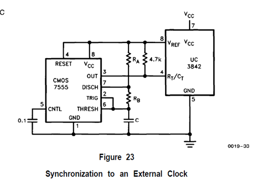
  

  • .  UCC2805 with injected voltage spike in series with the resistor per pp. 5-6 of this app note …


    U-133A UCC3800/1/2/3/4/5 BiCMOS Current Mode Control IC's
    Application Notes: http://www.ti.com/litv/pdf/slua149

  • Just an added comment to SLUA149:

    If you are injecting the pulse directly into the pin do not exceed the Vref voltage of the UCC2805. The common mode operation range of the internal error amp is not specified or measured but it is powered off the Vref rail internally so leave head room. Since the schematic for the comparator shows a 2.5 volt trip level  I would limit it to about 3.5 volts as a maximum voltage.

    In your diagram I would connect the 4.7kohm resistor from Rt/Ct to ground and change it to about 3 kohms I would place a 2 kohm resistor from out to the Rt/Ct pin.  This 2 kohm resistor is needed to limit the current into the pull down FET internal to the UC3805.

    The RA, RB, and C components should be chosen to provide a short duration (100 ns is ideentified in the app note but with the resistors you may need to have more)  positive pulse at the correct frequency.

    You will have to test to verify operation.

    regards,

    John

    .


  • I have to revise my answer after reviewing the internal structure of the UCC2805.

    My concern was that the voltage out of the 7555 would overdrive the internal comparators of the UCC2805. I went over the circuit with our aftermarket engineering team this morning and found it will not have that problem.

     My second concern was that if the output of the 7555 when high was applied to the Ct pin it would have enough drive capability to damage the internal discharge transistor.  Again aftermarket engineering and I reviewed the size of the internal FET. They do not at this point have any concerns.

     With the customers circuit as proposed they should be successful.

     When the pulse from the 7555 goes high, the UCC2805 will trigger holding the Ct voltage at approximately 1 volt until the 7555 pulse goes away.  When the 7555 pulse goes low the Ct voltage will drop below the 0.2 volt detect level turning off the internal discharge FET of the UCC2805 until the next pulse from the 7555.

     For thermal reasons it would be wise to keep the pulse out of the 7555 small.

    Regards

    John