This thread has been locked.

If you have a related question, please click the "Ask a related question" button in the top right corner. The newly created question will be automatically linked to this question.

LM22670-5 regulation problem under load

Other Parts Discussed in Thread: LM22670

Hi,

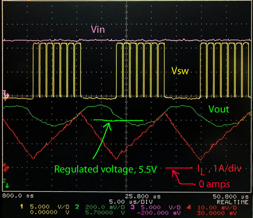
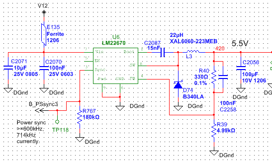
I have an LM22670-5 regulator application.  When I load it with a 1-1.4 amp load it tends to kick off for 7 usec every 27usec.

The inductor current is ramping up to  ~2.4A, which is well below the current limit.

The output voltage waveform does lag the current ramp and overshoots the regulated value by about 150mV.  I did not have any cap on the upper FB resistor so I added 100nF, which did not change anything.

The regulator is synced to an external 714kHz clock.

Any ideas?  Waveforms and circuit attached:

  • I am working on a circuit for another post right now, but I will take a look at this later tonight.


    Regards,

    Marc


  • Hi David,

    My first thought based upon the waveform is that the design looks unstable. Looking at a reference design on Webench, I see it recommends a 56uF capacitor with 40mohms of ESR.  This would place a zero at 1/(2*pi*55e-6*0.04) = 71Khz..  The zero would add phase margin to the design and improve stability.

    I would try adding 20mohms of resistance in series with your ceramic output capacitor to mimic the higher resistance I see on the webench design.  

    Let me know if this helps. 

    I will try to locate a board and build up the design.


    Regards,

    Marc


  • My Webench design calls out a 100uF cap with lower ESR limit of 15mOhms.  Are you able to access that design?

    http://webench.ti.com/webench5/power/webench5.cgi?DesignId=52&base_pn=LM22670

    I'll try adding some more mOhms.

  • I can't access the design from that link. It sends me to my own designs on webench. You can send designs to others using the share design button in the right hand corner of webench.

    Let me know if the additional ESR makes the design stable.  I have located a board, and can modify it to your design if this does not solve your problem.

    Regards,

    Marc


  • I changed the 100uF ceramic for a 100uF OS-CON.  That seems to have done the trick.

    In the design I may want to keep the ceramic cap and use a real resistor for the ESR so that the amount of ESR added is well controlled and minimal.  I will place the ESR between the inductor and the cap, and take the feedback ahead of the ESR resistor, and place the load on the cap directly.

    Thanks.

  • I know this is an old issue but I'm finding I need to make the ESR much larger than expected to tame the cycles down.  0.027 ohms is not quite enough.  0.039 seems barely enough, and 2x that seems better.  The webbench design indicates a 15 - 107 mohm range as acceptable.  Any ideas why I am needing to increase this ESR so high?