


Hi, this is my first post in this forum, so I will try not to be too much off-topic.
I have some doubts about the LM5100 FET driver (from National) that I would like to have some advices.
http://www.ti.com/product/lm5100a
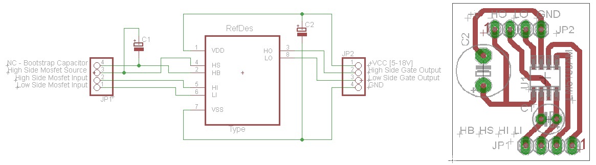
I build a small prototype board just with the chip LM5100 and 2 capacitors, in order to do some tests with MOSFETs and IGBTs.
The current configuration is:
1 - An Arduino is programed to generate and sinusoidal wave (configured by pushbuttons) from 2-100Hz, with commutation frequency also selectable from 1kHz to 4kHz.
2 - The 2 outputs from the Arduino (inverted and non-inverted) of 5V are directly connected to the LM5100 inputs (LI and HI). The LM5100 board has 1 electrolitic 10uF, 63V capacitor between Vdd and Vss, and also a bootstrap electrolitic capacitor of 1uF, 63V between HB and HS.
3 - On the output of the LM5100 I already succesfully tested to directly connected some LEDs, and a pair of IRFZ44N. My plan is to use the configuration to test the limitis of some MOSFET and IGBTs, so later I can build something bigger.
Now my questions:
a - Can I use LM5100 for something more serious like a full bridge PWM controller of a 1000W DC Motor, or a AC inverter for 3Ph Induction Motor? Or it is restricted to DC/DC chargers and rectifiers?!
b - Concerning point 2, I have no idea if I should use electrolic or ceramic capacitors. I know that they should be low ESR... And what about recomended values? the LM5100 datashet has no reference to that.
c - I it correct to assum that an MOSFET Driver can be use without restrictions to drive some IGBTs?!
d - This test board I build just work with the supply voltage between 7 and 11V! Why it can´t reach the 18V indicated in the datasheet!?!? It is an "hand built" PCB, probably with some parasitic currents between tracks... but I imagine that could be relevant only for high frequencies...
Thanks for your support!
LPereira
