This thread has been locked.

If you have a related question, please click the "Ask a related question" button in the top right corner. The newly created question will be automatically linked to this question.

Bq25504 problem

Other Parts Discussed in Thread: BQ25504

Hi,

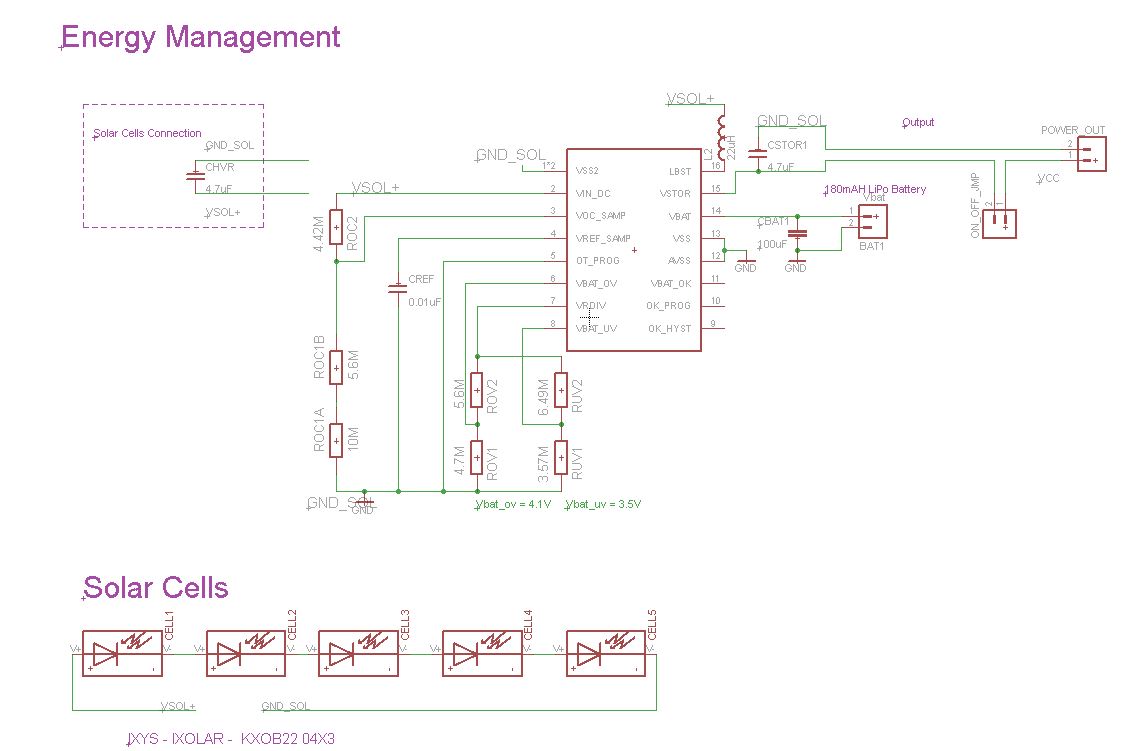
I would like some help with the bq25504 energy harvester. I would like it to charge a small LI-PO battery (fullriver 20mAh 20C max discharge rate) with a solar cell (KXOB22-4x3, Voc= 1.89V, 15mah). I prepare a board with the circuitry following the datasheet (a mix between figures 2 and 3) and evk  user’s guide. These are the resistors (megaohms) used to control the different voltage thresholds (megaohms):

UV: Ruv2=6.19 Ruv1=3.83 to give a voltage of 3.27V

OV: Rov2=5.62 Rov1=4.42 to give a voltage of 4.25V

Ok: Rok1=3.32 Rok20=6.19 Rok3=0.499 to give a voltage o 3,58V

Mppt Roc2=15 Roc1=4.42

The inductor used is Bourns SRU3028-220Y (22microH, tolerance 30%, DCR 270mohms, 0.6 A,SRF 15Mhz)

When I connect the solar cell and battery and the later did not charge(I leave for an hour at direct sunlight). I try a cold start to check the circuit and when the cell reach 1.8V, voltage at the Cstor quickly increase to reach 4.19V so I suppose that all is correct in board.

Which could be the cause of the fail to charge the battery?

In case I don’t use the Batok signal  , should I leave pin 11 unconnected or connected to ground? In such case could I leave pin 10 and pin 9 unconnected or connected to ground?

Thank you in advance

All the best

  • If using a solar cell the OC values should be set around 80% like on the EVM.

    The BATOK output can be left floating.

    Will have to find out if pins 9 and 10 can be left floating.


  • First of all thank you very much for your reply.

    With the resistor values used in Voc_samp is set to 0,77. The solar panel used is 1,89V so the VOC would be 1.46V (in the datasheet is stated that Vmppt is 1.5V). So I think that is correct, isn't it? I would try to change the resistor value to reach a value nearer to 80%.

    Should I used some special configuration (more than set UV and OV) with high discharge rate li-po batteries? In my design is like the problem would be with the battery because the boost converter rises the voltage of VSTOR to OV level in a cold start without battery.

    Thanks again 

  • The UV threshold is where the Vbat is disconnected from the Vstor.  All the load should be on Vstor.

    The BATok signal is typically used to disable the load when it goes low.  If Vstor is discharge below ~1.8V, then the part will start up up cold start which is not very efficient.

    If there is a system load during cold start, the part make get stuck in cold start.


    If the pins 9, 10 and 11 are not used, pins 9 and 10 can be tied to Vstor with no resistor required.

  • Thanks!! This would save space in the board!!

    What could cause of the absence of battery recharge? I have the load tied to VSTOR .

  • Is Vstor less than UV?  If Vstor is above UV then the FET between Vstor and Vbat (Vuv>2.199V) should be on.

  • No, when I connect the battery VSTOR is equal to the voltage of the battery, in this case 3.7V. If the battery is not connected and Vin>1.8V then VSTOR an the voltage of Vbat =BATOV=4.2V

  • I am facing the same mis adventures, unable to charge a Lipo battery with this BQ25504 and KXOB22 Solar Cells ... 

    What has been the outcome of your tests ? Could you successfully charge the Lipo battery ?

  • Hi,

    I successfully charge the lipo. All the circuit works correctly but I was using a very low intensity light and the module cannot charge. When I used natural light I realize that all was fine. How is your schematics?

  • This is my schematic .. I measured the input current to the LiPo and it is less than 1mA ... which obviously will never charge the battery ...

  • Check the voltage on VIN.  It should be regulating to the percentage of the open circuit voltage that you set with the MPPT resistors.  If not, it could be leakage from the capacitor on the VREF samp pin.  

     during board assembly, contaminants such as solder flux and even some board cleaning agents can

    leave residue that may form parasitic resistors across and/or from one end of the resistor/capacitor to

    ground, especially in humid, fast airflow environments. This can result in the voltage regulation and threshold

    levels changing significantly from those expected per the installed resistor values and capacitors discharging. Therefore, it is highly

    recommended that no ground planes be poured near the voltage setting resistors. In addition, the boards must

    be carefully cleaned, possibly rotated at least once during cleaning, and then rinsed with de-ionized water until

    the ionic contamination of that water is well above 50 MOhm. If this is not feasible, then it is recommended that

    the sum of the voltage setting resistors be reduced to at least 5X below the measured ionic contamination.


  • These aspects you mention seem a bit far fetched to me as I've never had any experience in this domain but if that is the case I don't know how to continue from here.

    I've ordrered my PCB and they are good quality and then I use a reflow oven to solder the QFN, everything else is hand soldered, flux is added sometimes in small quantities and cleaned afterwards ... 

    But I have more the feeling that the output current is limited, nothing near 10mA but closer to 0.1mA ... could it be that the Inductor is undersized ? I have this one : Taiyo Yuden CBC2012T220K which specs are 22UH, 170mA, 10%, 16MHZ so this looks good to me... 

    I guess there is no other special requirement when trying to charge a LiPo battery ? I mean If you put 4.1V accross its terminals then the current should be flowing and charging it we no ?


  • Inductor saturation current is a bit low.  Slightly larger than 300mA would best.

    Also, board assembly problem is real.  I make these EVMs for TI and had to rewash an entire batch due to contaminants after assembly.  Large resistors are always a problem.  But that cap on VREF_SAMP is critical to the IC functionality. 

    As I mentioned before, check the voltage on VIN.  It should have some ripple but not much, except when the MPPT activates every 16s.

  • Ok Thanks,

    Jeff F said:
    had to rewash an entire batch due to contaminants after assembly

    I cleaned everything and will try again now..

    Jeff F said:
    As I mentioned before, check the voltage on VIN.  It should have some ripple but not much, except when the MPPT activates every 16s.

    The voltage on VIN is like a proper DC voltage with little to no ripples at all ...

    A new question came to my mind, for VBat I used a 100uF capacitor in parallel with a LiPo 180mAh  battery, but I tried to remove the capacitor it doesn't charge any better, though the capacitor alone charges well ( probably because even a few uA are enough to charge it quickly ...)

    My VREF_SAMP cap is a 10nF cap nothing special to it ... 

  • Regarding the wash, I had to find a special board assembler with the ability to wash to 50Mohm sensitivity.  If the VIN voltage appears to be regulated with low ripple, then the capacitor is not leaking so board wash is not the problem. The capacitor itself should be low leakage so either X7R or COG.  To what voltage does VIN regulate?  Is this voltage the appropriate percentage of VOC that you set per the MPPT resistors?

    Regarding the battery charge current, you mentioned that you only measured about 1mA.  Is there a load on VSTOR that is robbing some of the charge current to VBAT?  The leakage current of the battery itself will look like a dc load on VBAT=VSTOR but if you are measuring current from VBAT into the battery, you would measure that too.

    You can use the following power/efficiency balance to predict the amount of current into VSTOR and/or VBAT:

    (VSTOR*ISTOR) / (VIN *IIN) = efficiency where you you can get estimates from the datasheet curves.  IIN will be a function of ambient energy available to your harvestor.

  • I narrowed down my problem to my solar cells .. because I replaced the solar cell with a power supply and everything worked well... I am glad I don't seem to have troubles with the flux or whatever else... 

    When testing with that power supply I estimated the efiiciency to be arround 75% .. which is slightly below the specs but reasonable..

    Though My question comes now to Jose M as you mentioned using  

    Jose M�� Abad Gomez-Pantoja said:
    with a solar cell (KXOB22-4x3, Voc= 1.89V, 15mah).

    I'd like to know if you reached the 15mA of Short Circuit current ?  Because I get nowhere near that value .. it is Max 2mA outside with a cloudy sky but still bright .. could it be that with a sunny sky I reach 15mA ? I doubt it ...

    I am very confused about the efficiency of these cells ... 

    Obviously because I only have around 3V@2mA I get an output to charge the battery of 4.15V@~0.8mA which is maybe gonna charge the battery after 2 weeks ... haha

  • That was also my approach and when I put the solar cells under direct sunlight I got the maximum short circuit current. Even small clouds or something that cover partially the sun will reduce exponentially the current. Also the angle of the cells could reduce drastically the current. Try to expose to direct sunlight and probably you get the results you are looking for. I got other solar cells (TASC cells) that are lighter, a bit bigger but provide higher voltage ( Vop 2.52 V) and current (Isc 31ma), with two of these cells I get 15-20 ma in vbat in a bright sunny day. With these same cells in a cloudy but bright day I only can get 1-5 ma.

    Hope this helps

    PD sorry for the english!!