This thread has been locked.

If you have a related question, please click the "Ask a related question" button in the top right corner. The newly created question will be automatically linked to this question.

TPS2590 Slow Turn Off under Short Circuit

Other Parts Discussed in Thread: TPS2590

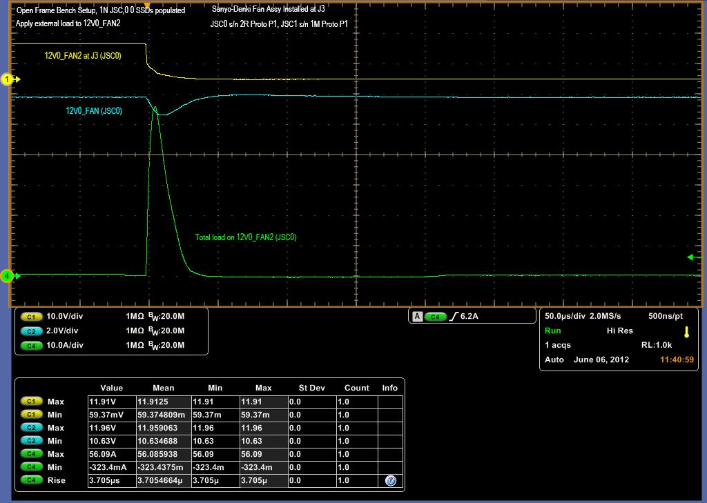
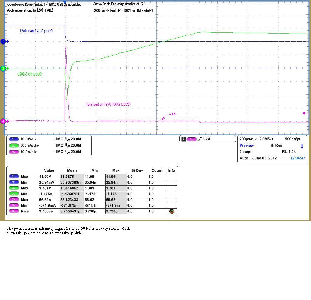
When I apply an abrupt short to the output of the TPS2590 the device is very slow in turning off which results in very high currents. The current limit level is set to 3A nominal and the peak current under a hard short is 56A. The fall time of the 12V output is on the order of 30us. Does anyone know what could cause such a long turn off time? I would have expected a turn off time to be approximately 1us. How long can it take to turn off a fet?

2553.jsc_schematic_7041647_12V0_FAN_TPS2590.pdf

  • What is the value you are using for Ct (pin 9)?

    Did you try to make Ct smaller to achieve a smaller fault time?

  • Ct is 0.022uF. I did not try to make Ct smaller as the high current event is very fast and Ct has hardly ramped up. If you look at my previous post you will see there is a link to the schematic; it's above the picture.

    I've attached another picture showing the voltage on Ct. There is a big negative voltage surge on Ct during the high peak current event, which I am not sure if this is related to the problem. Perhaps the TPS2590 loses control due to coupling into Ct. After the high peak current Ct regains its composure and ramps up as expected until the 1.4V threshold is reached and the output is turned off.

  • Here's another picture zooming in on an overload event. An electronic load was used instead of a hard wire short. The electronic load was set from 0A to 30A at a slew rate of 1A/us. The fall time of the output (12V0_FAN2) is 30us which is extremely long. Note that the voltage on CT does not surge negative. The setup is different from previous picture, so maybe I had some high ground currents induced between probes. I'll take a closer look at the setup and try to use one common ground point.

  • I think that the fact that VCt goes negative for the hard short... could explain the issue. Again, did you try a different Ct value for the electronic load scenario, to see if it affects the shutdown time? Do you think that something in the layout could explain the coupling to VCt for the hard shortcircuit?

  • Lance, at which circuit point are you measuring current? Did you measure into IN (between any 12VO_FAN and IN pins of TPS2590) or out of OUT (between TPS2590 and OUT capacitance)? This is the true current that TPS2590 looks at.

    Also, the "inductive" ringing on CT implies/indicates a potential layout or grounding problem.

  • The current is measured in the wires going to the external electronic load. The original picture shows the current through the TPS2590 along with the discharge current in C470 10uF load capacitor. I ran another overload event with the 10uF cap removed and the current dropped significantly, so the 10uF cap is a significant contributor to the short current. The peak current dropped from 38.76A down to 23.55A, but this is still very high and I would like to understand it.

    In the picture below, the 10uF cap (C470) is removed and the external electronic load is set to step load from 0A to 30A at 1A/us. The input voltage (12V0_FAN) is monitored right on the input pins during the event and a voltage drop of 0.46V is seen with waveform in phase with the current. The net ESR of the two 4700uF caps is ~ 30m-Ohms and the peak current is ~(23.55A-8.3A) = 15A for an expected drop of 0.03-Ohms*15A = 0.45V which is close to the 0.5V measured drop during the event.

    I believe the negative spike on CT in the original picture was a measurement error with how the probe grounds were hooked up. I was using a 12" jumper to short the output and did not use one single point for all my probe grounds. I had one probe ground that would have seen a big voltage drop when the short was applied, so that corrupted the measurement. The later pictures replace the ground wire with an electronic load and the probe grounds all use one common return on the card. There is no longer any negative voltage spike on CT.

    What is normal operation for how fast the TPS2590 should respond to an over-current? I was expecting the TPS2590 to current limit within ~1us, but there is nothing in the spec for this timing.

    **********************************************************************************************************

    Schematic:

    **********************************************************************************************************

    A suggestion was made to reduce the value of the CT capacitor, but I don't see how this will affect this initial current spike so I have not done this yet. If we can't figure out why the TPS2590 is taking so long to turn off and allowing a huge surge current, then I will reduce CT to see what impact it might have on the turn off time.

    I've attached the layout. I don't see any issues, but take a look at it.

  • Lance, thanks for the info. Unfortunately, I don't think we can solve this over E2E (even though that is my preference). Can you send us a board to look at?