This thread has been locked.

If you have a related question, please click the "Ask a related question" button in the top right corner. The newly created question will be automatically linked to this question.

TPS54418RTET

Other Parts Discussed in Thread: TPS54618, TPS54478, TPS54218

Hi,

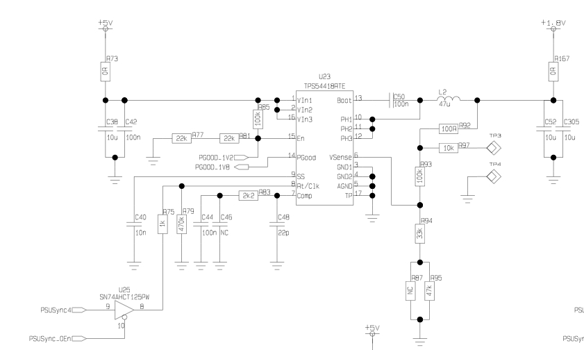
We are experiencing some issues with the TPS54418RTET on some of our units.

Configuration:

Vin=5V

Vout=1.8V

Load=~40mA

The regulator output voltage is correct, but the duty cycle is somewhat irregular (see figure 1 below).

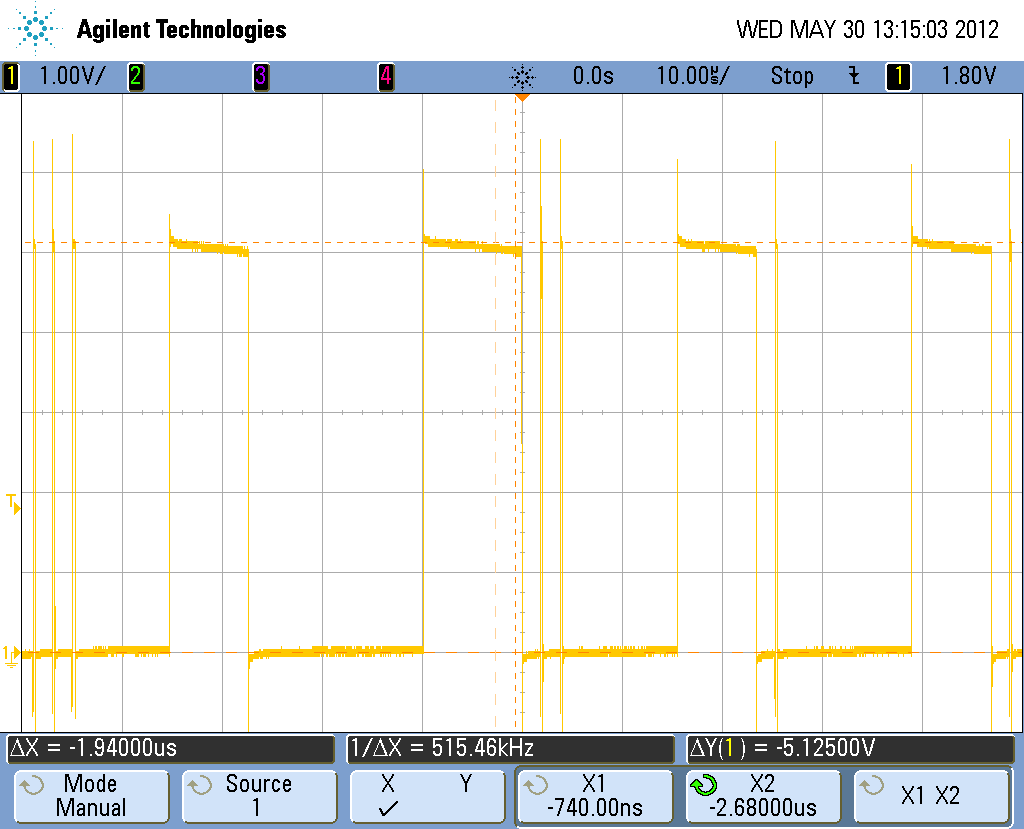
Figure 1 - Irregular output

This is no problem, however, until a bigger load is switched on (~300mA). The duty cycle changes to a more regular pattern, but in the meantime the output voltage drops by  over 10% before settling back to 1.8V after about 1.5ms.

Figure 2 - Duty cycle at higher loads

Can anyone provide an explanation as to what may be the cause of this? Anyone seen this before? I will happily provide more details if needed...

Edit: added the duration of the voltage drop

  • I have seen somewhat similar conditions, but that first waveform does not look exactly the same.  So it may be possible there is some other issue.  On thing to try is when you are in the light load condition, heat the circuit slightly.  Does teh PH waveform return to normal?  You may also want to post your schematics.

  • Thank you very much for the reply!

    I did notice that heating the circuit actually does make everything better while trying to modify the configuration, but as soon as it cools the PH returns to this irregular pattern. Also, after applying a high load and henche changing the duty cycle to normal, it is possible to reduce the load somewhat while maintaining a stable PH pattern. Reducing it too much, though, and it will return to an irregular duty cycle.

    The configuration can be found below:

    *Please note that the Cout is not completely shown here, there are several other capacitors attached, most notably a 1mF low ESR cap in order to handle the switching.

    Is there anything I can do with the configuration to prevent this phenomenon from occurring? This is currently affecting almost 2% of our units.

  • Hi Thomas,

    I think your applicaiton circuit may run into the large singal instability issue of this part seen mostly at high Vin, light loads and cold temp on a very small percentage of parts. The instability manifests itself in the form of an irregular PH waveform which leads to high ripple on Vout. Increasing the load current, increasing the temperature, decreasing Vin result in the elimination of the instability.

    When PH flies high with an uncontrolled slew rate due to recirculation current from inductor, the parasitic cap of internal node in the BOOT-PH UVLO circuit cause a significant dip in the bias current to the Itrip block and also cause a glitch on the BOOT-PH UVLO output to shut off high-side FET. The instability in Phase is seen as a result of the decreased bias current to the current sense comparator or BOOT-PH UVLO glitch.

    This happens at high Vin because the slew rate on PH is highest.

    This happens at light load for two reasons:

    1) When there is negative inductor current, it will recirculate through the high side body diode when the low side shuts off—no control on slew rate of PH and capacitive coupling becomes worse.

    2) Variation of bias current becomes larger portion of total internal measured current.

    This happens at cold temp for two reasons:

    1) The Vgs threshold is highest. Small dip on Vgs due to the internal parasitic cap when PH flies high can cause BOOT-PH UVLO glitch at cold temp.

    2) The Rdson is lowest--low rdson increases the common mode of the sense comparator and is at the point of highest sensitivity to any fluctuation in bias current

    There is no reliability concern because of this issue. If Vout ripple is out of the spec, increasing the output cap may help. If you are still concerned about it, the TPS54478 or TPS54618 are recommended as a replacement.

    The majority of the parasitic cap is due to a probe pad sitting over substrate connected metal 1. When this probe pad was cut out on a failing unit, the unit recovered and operated properly over all conditions. We are in the process to implement the change and hopefully it will be in the production early Q4 2012.

    Regards,

    Na

  • Hi Na,

    Thank you for a very good answer! I will look into your suggested workarounds.

  • Does this parasitic cap problem impact all parts in this series and are they all being updated?

  • TPS54218/318/418 only are affected.  I am not sure about the update schedule.

  • Hi,

    Our product, using the the TPS54218, is also suffering from a similar low temperature issue. Is there anything new regarding the update schedule for these components?

    Thanks

  • The TPS54218 change has been implemented. Please contact your local sales office for more information